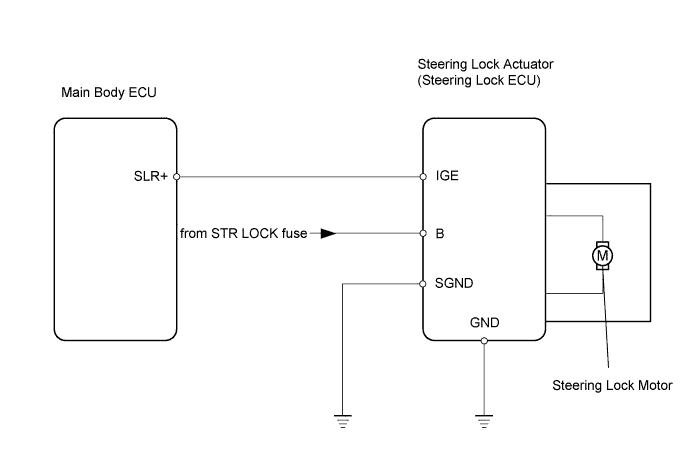
STEERING LOCK SYSTEM > Steering Lock Motor Drive Power Circuit |
| 1.CHECK DTC (CERTIFICATION ECU) |
Connect the intelligent tester to the DLC3.
Turn the engine switch on (IG) and press the intelligent tester main switch ON.
Read the DTCs of the certification ECU by following the prompts displayed on the intelligent tester.
|
| ||||
| OK | |
 |
| 2.READ VALUE USING INTELLIGENT TESTER (CERTIFICATION ECU) |
Connect the intelligent tester to the DLC3.
Turn the engine switch on (IG) and press the intelligent tester main switch ON.
Select the item "Lock/Unlock Receive" in the Data List within 10 seconds of starting the engine and read the value displayed on the intelligent tester.
| Item | Measurement Item / Range (Display) | Normal Condition | Diagnostic Note |
| Lock/Unlock Receive | Steering lock command reception record / YES or NO | YES: Steering lock/unlock signal received NO: Steering lock/unlock signal not received | - |
|
| ||||
| OK | |
|
| 3.CHECK STEERING LOCK ACTUATOR |
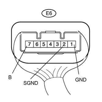 |
Measure the resistance and voltage of the steering lock actuator.
| Tester Connection | Specified Condition |
| E6-1 (GND) - Body ground | Below 1 Ω |
| E6-2 (SGND) - Body ground | Below 1 Ω |
| Tester Connection | Specified Condition |
| E6-7 (B) - E6-1 (GND) | 11 to 14 V |
| E6-7 (B) - E6-2 (SGND) | 11 to 14 V |
|
| ||||
| OK | |
|
| 4.CHECK STEERING LOCK ACTUATOR |
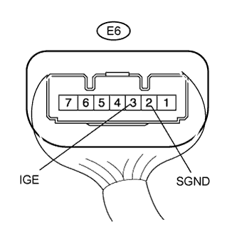 |
Immediately after turning the engine switch on (IG), inspect the voltage between terminals E6-3 (IGE) and E6-2 (SGND) of the steering lock actuator.
| Result | Proceed to |
| Immediately after turning engine switch on (IG), condition that measurement is 1 V or less occurs | A |
| Measurement is 11 to 14 V, and measurement never becomes 1 V or less | B |
|
| ||||
| A | ||
 | ||
| ||
| 5.READ VALUE USING INTELLIGENT TESTER (CERTIFICATION ECU) |
Connect the intelligent tester to the DLC3.
Turn the engine switch on (IG) and press the intelligent tester main switch ON.
Select the item "S Code Check" in the Data List and read the value displayed on the intelligent tester.
| Item | Measurement Item / Range (Display) | Normal Condition | Diagnostic Note |
| S Code Check | S code match record / NG or OK | NG: S code not matched OK: S code matched | - |
|
| ||||
| NG | |
|
| 6.CHECK OPERATION OF ID CODE BOX |
Replace the ID code box with a normally functioning or new one.
Reconfirm the item "S Code Check" in the Data List and read the value displayed on the intelligent tester.
| Item | Measurement Item / Range (Display) | Normal Condition | Diagnostic Note |
| S Code Check | S code match record / NG or OK | NG: S code not matched OK: S code matched | - |
|
| ||||
| NG | ||
| ||
| ||
| 7.READ VALUE USING INTELLIGENT TESTER (CERTIFICATION ECU) |
Connect the intelligent tester to the DLC3.
Turn the engine switch on (IG) and press the intelligent tester main switch ON.
Select the item "L Code Check" in the Data List and read the value displayed on the intelligent tester.
| Item | Measurement Item / Range (Display) | Normal Condition | Diagnostic Note |
| L Code Check | L code match record / NG or OK | NG: L code not matched OK: L code matched | - |
|
| ||||
| NG | |
|
| 8.CHECK OPERATION OF ID CODE BOX |
Replace the ID code box with a normally functioning or new one.
Reconfirm the item "L Code Check" in the Data List and read the value displayed on the intelligent tester.
| Item | Measurement Item / Range (Display) | Normal Condition | Diagnostic Note |
| L Code Check | L code match record / NG or OK | NG: L code not matched OK: L code matched | - |
|
| ||||
| NG | |
|
| 9.CHECK OPERATION OF STEERING LOCK ACTUATOR |
Replace the steering lock actuator assembly with a normally functioning or new one.
Turn the engine switch on (IG).
Check the steering lock.
|
| ||||
| NG | ||
| ||
| ||

