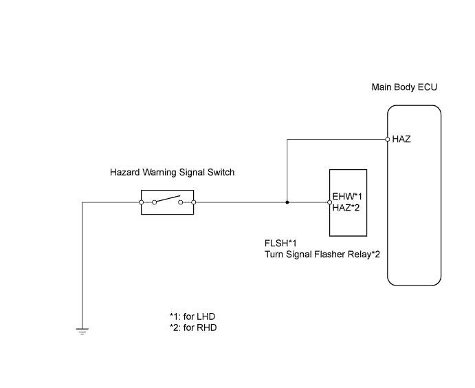
WIRELESS DOOR LOCK CONTROL SYSTEM (w/ Entry and Start System) > No Answer-Back |
| 1.CHECK WIRELESS DOOR LOCK CONTROL FUNCTION |
Check the wireless door lock control functions by operating the transmitter switches.
| Result | Proceed to |
| Wireless door lock functions are normal but hazard warning light answer-back does not occur | A |
| Wireless door lock functions are abnormal | B |
|
| ||||
| A | |
 |
| 2.PERFORM ACTIVE TEST USING INTELLIGENT TESTER (FLSH RELAY, TURN SIGNAL FLASHER RELAY) |
Select the Active Test, use the intelligent tester to generate a control command, and then check that the hazard warning lights flash.
| Item | Test Details | Diagnostic Note |
| Hazard | Turns FLSH relay*1 (turn signal flasher relay*2) ON / OFF | - |
|
| ||||
| NG | |
|
| 3.CHECK HAZARD WARNING LIGHT |
Check that the hazard warning lights flash continuously when the hazard warning signal switch is pressed.
| Result | Proceed to |
| Hazard warning lights flash continuously (for RHD) | A |
| Hazard warning lights do not flash continuously | B |
| Hazard warning lights flash continuously (for LHD) | C |
|
| ||||
|
| ||||
| A | |
|
| 4.CHECK WIRE HARNESS (MAIN BODY ECU - TURN SIGNAL FLASHER RELAY) |
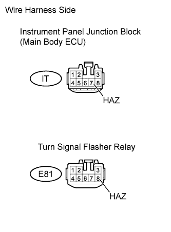 |
Disconnect the IT junction block connector.
Disconnect the E81 flasher connector.
Measure the resistance of the wire harness side connectors.
| Tester Connection | Specified Condition |
| IT8-7 (HAZ) - E81-8 (HAZ) | Below 1 Ω |
| IT8-7 (HAZ) or E81-8 (HAZ) - Body ground | 10 kΩ or higher |
|
| ||||
| OK | ||
 | ||
| ||
