 |
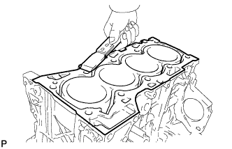
Using a gasket scraper, remove all the gasket material from the top surface of the cylinder block.
CYLINDER BLOCK > INSPECTION |
| 1. INSPECT NO. 1 OIL NOZZLE SUB-ASSEMBLY |
Check the oil nozzles for damage or clogging.
If there is damage or clogging, replace the oil nozzle.
| 2. CLEAN CYLINDER BLOCK SUB-ASSEMBLY |
|
Using a gasket scraper, remove all the gasket material from the top surface of the cylinder block.
Using a soft brush and solvent, thoroughly clean the cylinder block.
| 3. INSPECT CYLINDER BLOCK FOR WARPAGE |
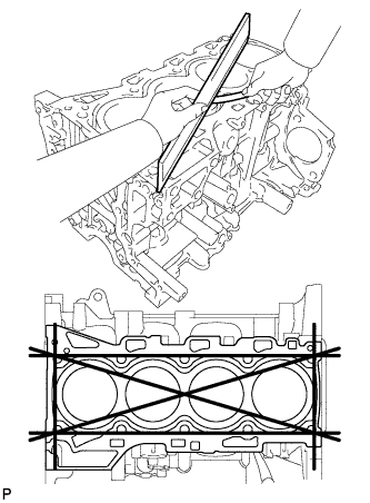 |
Using a precision straightedge and feeler gauge, measure the warpage of the surface where the cylinder head gasket contacts the cylinder head.
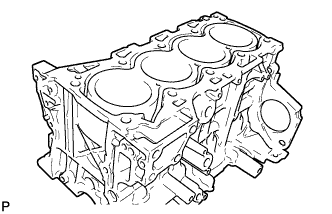 |
Visually check the cylinders for vertical scratches.
If deep scratches are present, replace the cylinder block.
| 4. INSPECT CYLINDER BORE |
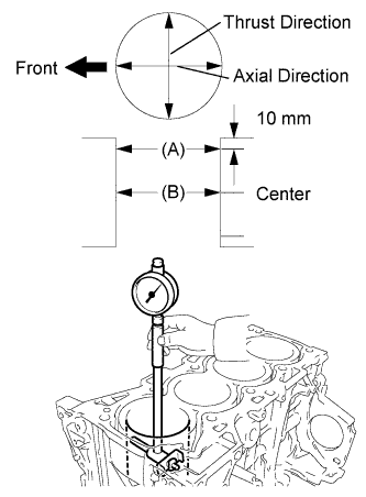 |
Using a cylinder gauge, measure the cylinder bore diameter at positions A and B in the thrust and axial directions.
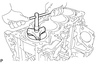 |
Inspect the cylinder ridge.
If the wear is less than 0.2 mm (0.00787 in.), using a ridge reamer, grind the top of the cylinder.
| 5. CLEAN PISTON |
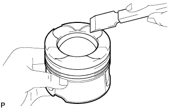 |
Using a gasket scraper, remove the carbon from the piston top.
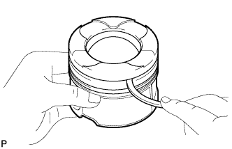 |
Using a groove cleaning tool or broken ring, clean the piston ring grooves.
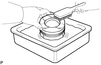 |
Using solvent and a brush, thoroughly clean the piston.
| 6. INSPECT PISTON DIAMETER |
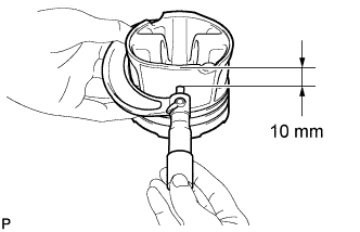 |
Using a micrometer, measure the piston diameter at right angles to the piston center line where the position is 10 mm (0.394 in.) from the bottom edge of the piston.
| 7. INSPECT PISTON OIL CLEARANCE |
Measure the cylinder bore diameter in the thrust direction.
Subtract the piston diameter measurement from the cylinder bore diameter measurement.
| 8. INSPECT RING GROOVE CLEARANCE |
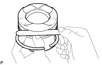 |
Using a feeler gauge, measure the clearance between a new piston ring and the wall of the ring groove.
| Ring | Specified Condition |
| No. 1 | 0.095 to 0.135 mm (0.00374 to 0.00531 in.) |
| No. 2 | 0.03 to 0.12 mm (0.00118 to 0.00472 in.) |
| Oil | 0.03 to 0.07 mm (0.00118 to 0.00276 in.) |
| 9. INSPECT PISTON RING END GAP |
Insert the piston ring into the cylinder bore.
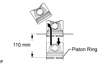 |
Using a piston, push the piston ring a little beyond the bottom of the ring travel 110 mm (4.33 in.) from the top of the cylinder block.
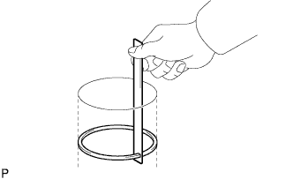 |
Using a feeler gauge, measure the end gap.
| Ring | Specified Condition |
| No. 1 | 0.22 to 0.32 mm (0.00866 to 0.0126 in.) |
| No. 2 | 0.47 to 0.62 mm (0.0185 to 0.0244 in.) |
| Oil | 0.1 to 0.40 mm (0.00394 to 0.0157 in.) |
| Ring | Specified Condition |
| No. 1 | 0.92 mm (0.0362 in.) |
| No. 2 | 1.22 mm (0.0480 in.) |
| Oil | 1.06 mm (0.0417 in.) |
| 10. INSPECT PISTON PIN OIL CLEARANCE |
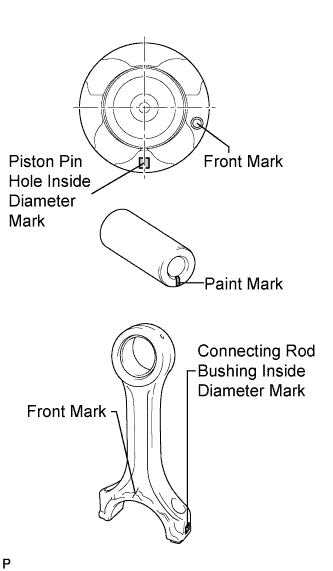 |
Check each mark on the piston, piston pin and connecting rod.
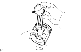 |
Using a caliper gauge, measure the inside diameter of the piston pin hole.
| Mark | Specified Condition |
| A | 29.009 to 29.013 mm (1.1421 to 1.1422 in.) |
| B | 29.013 to 29.017 mm (1.1422 to 1.1424 in.) |
| C | 29.017 to 29.021 mm (1.1424 to 1.1426 in.) |
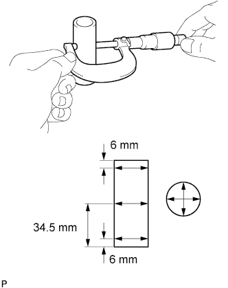 |
Using a micrometer, measure the piston pin diameter.
| Mark (Paint Color) | Specified Condition |
| A (White) | 29.000 to 29.004 mm (1.1417 to 1.1419 in.) |
| B (Pink) | 29.004 to 29.008 mm (1.1419 to 1.1420 in.) |
| C (Blue) | 29.008 to 29.012 mm (1.1420 to 1.1422 in.) |
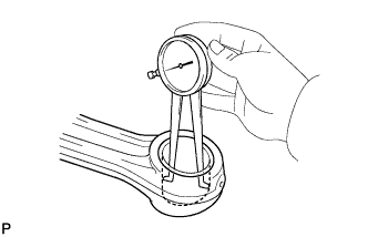 |
Using a caliper gauge, measure the inside diameter of the connecting rod bush.
| Mark | Specified Condition |
| A | 29.019 to 29.023 mm (1.1425 to 1.1426 in.) |
| B | 29.023 to 29.027 mm (1.1426 to 1.1428 in.) |
| C | 29.027 to 29.031 mm (1.1428 to 1.14230 in.) |
Subtract the piston pin diameter measurement from the piston pin hole diameter measurement.
Subtract the piston pin diameter measurement from the bush inside diameter measurement.
| 11. INSPECT CONNECTING ROD SUB-ASSEMBLY |
Using a rod aligner and feeler gauge, check the connecting rod alignment.
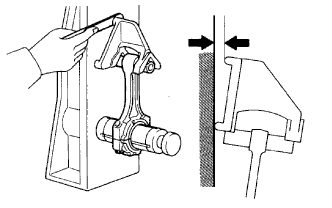 |
Check for bend.
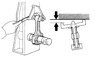 |
Check for twist.
| 12. INSPECT CONNECTING ROD THRUST CLEARANCE |
Install the piston with pin, piston ring set and connecting rod bearing .
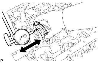 |
Using a dial indicator, measure the thrust clearance while moving the connecting rod back and forth.
Remove the connecting rod bearing, piston ring set and piston with pin .
| 13. INSPECT CONNECTING ROD OIL CLEARANCE |
Install the connecting rod bearing .
Install the crankshaft bearing .
Install the upper crankshaft thrust washer .
Install the crankshaft .
Clean the crank pin and connecting rod bearing.
Check the crank pin and connecting rod bearing for pitting and scratches.
Install the connecting rod.
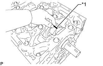 |
Lay a strip of Plastigage on the crank pin.
| *1 | Plastigage |
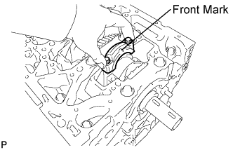 |
Check that the front mark (protrusion) of the connecting rod cap is facing forward and install the cap.
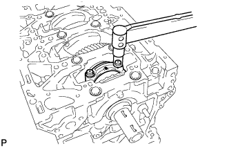 |
Install and alternately tighten the bolts of the connecting rod cap in several steps.
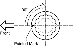 |
Mark the front side of each connecting cap bolt with paint.
Tighten the cap bolts by 90°.
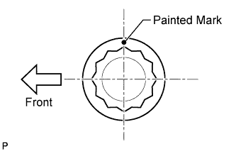 |
Check that the painted marks are now at a 90° angle to the front.
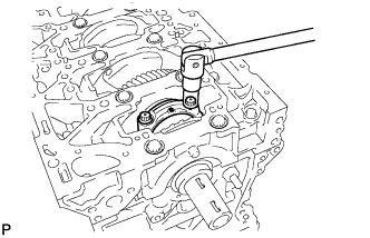 |
Remove the 2 connecting rod cap bolts.
Using the 2 removed connecting rod cap bolts, remove the connecting rod cap and lower bearing by wiggling the connecting rod cap right and left.
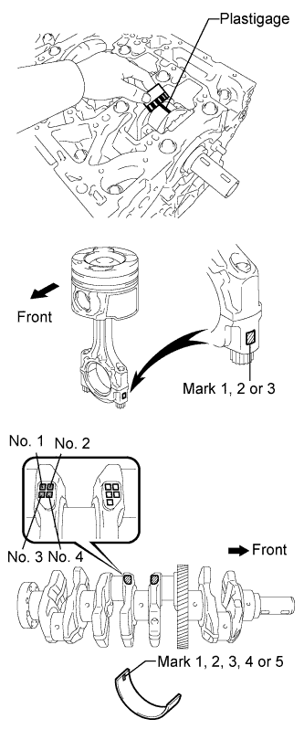 |
Measure the Plastigage at its widest point.
| Item | Number Mark | ||||||||
| Connecting rod cap | 3 | 2 | 3 | 1 | 2 | 3 | 1 | 2 | 1 |
| Crankshaft | 2 | 2 | 1 | 2 | 1 | 0 | 1 | 0 | 0 |
| Use bearing | 5 | 4 | 3 | 2 | 1 | ||||
| Mark | Specified Condition |
| 1 | 53.000 to 53.006 mm (2.0866 to 2.0869 in.) |
| 2 | 53.006 to 53.012 mm (2.0869 to 2.0871 in.) |
| 3 | 53.012 to 53.018 mm (2.0871 to 2.0873 in.) |
| Mark | Specified Condition |
| 0 | 49.994 to 50.000 mm (1.9683 to 1.9685 in.) |
| 1 | 49.988 to 49.994 mm (1.9680 to 1.9683 in.) |
| 2 | 49.982 to 49.988 mm (1.9678 to 1.9680 in.) |
| Mark | Specified Condition |
| 1 | 1.485 to 1.488 mm (0.0585 to 0.0586 in.) |
| 2 | 1.488 to 1.491 mm (0.0586 to 0.0587 in.) |
| 3 | 1.491 to 1.494 mm (0.0587 to 0.0588 in.) |
| 4 | 1.494 to 1.497 mm (0.0588 to 0.0589 in.) |
| 5 | 1.497 to 1.500 mm (0.0589 to 0.0591 in.) |
Completely remove the Plastigage.
Remove the connecting rod.
Remove the crankshaft .
Remove the upper crankshaft thrust washer .
Remove the crankshaft bearing .
Remove the connecting rod bearing .
| 14. INSPECT CONNECTING ROD BOLT |
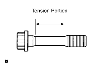 |
Using a vernier caliper, measure the tension portion diameter of the bolt.
| 15. INSPECT CRANKSHAFT |
Inspect for circle runout.
Place the crankshaft on V-blocks.
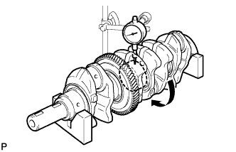 |
Using a dial indicator, measure the circle runout at the center journal.
Inspect the main journals.
Using a micrometer, measure the diameter of each main journal.
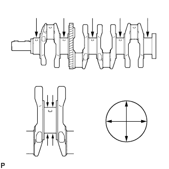 |
Check each main journal for taper and out-of- round.
Inspect the crank pin.
Using a micrometer, measure the diameter of each crank pin.
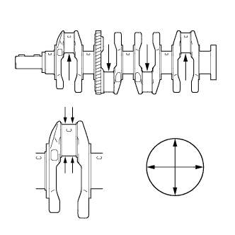 |
Check each crank pin for taper and out-of-round.
| 16. INSPECT CRANKSHAFT THRUST CLEARANCE |
Install the crankshaft bearing, upper crankshaft thrust washer and crankshaft .
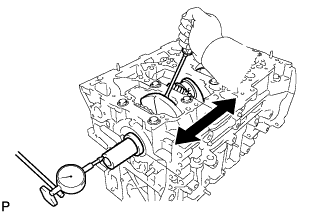 |
Using a dial indicator, measure the thrust clearance while prying the crankshaft back and forth with a screwdriver.
Remove the crankshaft, upper crankshaft thrust washer and crankshaft bearing .
| 17. INSPECT CRANKSHAFT OIL CLEARANCE |
Install the crankshaft bearing .
Install the upper crankshaft thrust washer .
Clean each main journal and bearing.
Check each main journal and bearing for pitting and scratches.
Place the crankshaft on the cylinder block.
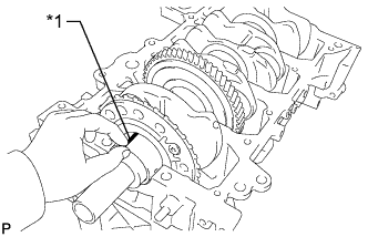 |
Lay a strip of Plastigage across each journal.
| *1 | Plastigage |
Place the crankshaft bearing cap assembly on the cylinder block.
Temporarily install the crankshaft bearing cap bolts.
Step 1:
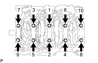 |
Uniformly tighten the 10 main bearing cap bolts in several passes, in the sequence shown in the illustration.
Step 2:
|
Mark the front of the bearing cap bolts with paint.
Tighten the bearing cap bolts by 90° as shown.
|
Check that the painted marks are now at a 90° angle to the front.
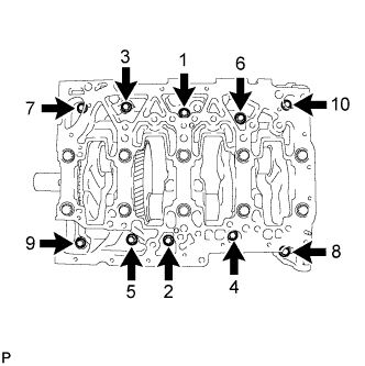 |
Install and uniformly tighten the 10 bolts in several passes, in the sequence shown in the illustration.
Remove the crankshaft bearing cap.
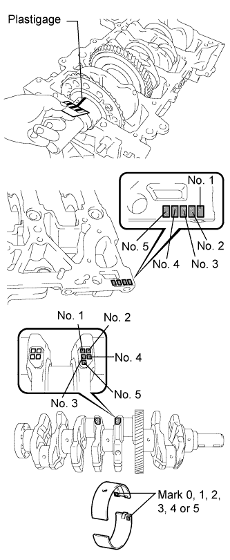 |
Measure the Plastigage at its widest point.
| Journal | Specified Condition |
| No. 3 | 0.020 to 0.038 mm (0.000787 to 0.00150 in.) |
| Others | 0.014 to 0.032 mm (0.000551 to 0.00126 in.) |
| Item | Number Mark | ||||||||
| Cylinder block | 2 | 2 | 1 | 2 | 1 | 0 | 1 | 0 | 0 |
| Crankshaft | 2 | 1 | 2 | 0 | 1 | 2 | 0 | 1 | 0 |
| Use bearing | 4 | 3 | 2 | 1 | 0 | ||||
| Item | Number Mark | ||||||||
| Cylinder block | 3 | 3 | 2 | 3 | 2 | 1 | 2 | 1 | 1 |
| Crankshaft | 2 | 1 | 2 | 0 | 1 | 2 | 0 | 1 | 0 |
| Use bearing | 5 | 4 | 3 | 2 | 1 | ||||
| Mark | Specified Condition |
| 0 | 63.000 to 63.006 mm (2.4803 to 2.4805 in.) |
| 1 | 63.006 to 63.012 mm (2.4805 to 2.4808 in.) |
| 2 | 63.012 to 63.018 mm (2.4808 to 2.4810 in.) |
| Mark | Specified Condition |
| 1 | 63.000 to 63.006 mm (2.4803 to 2.4805 in.) |
| 2 | 63.006 to 63.012 mm (2.4805 to 2.4808 in.) |
| 3 | 63.012 to 63.018 mm (2.4808 to 2.4810 in.) |
| Mark | Specified Condition |
| 0 | 58.994 to 59.000 mm (2.3226 to 2.3228 in.) |
| 1 | 58.988 to 58.994 mm (2.3224 to 2.3226 in.) |
| 2 | 58.982 to 58.988 mm (2.3221 to 2.3224 in.) |
| Mark | Specified Condition |
| 0 | 1.987 to 1.990 mm (0.0782 to 0.0783 in.) |
| 1 | 1.990 to 1.993 mm (0.0783 to 0.0785 in.) |
| 2 | 1.993 to 1.996 mm (0.0785 to 0.0786 in.) |
| 3 | 1.996 to 1.999 mm (0.0786 to 0.0787 in.) |
| 4 | 1.999 to 2.002 mm (0.0787 to 0.0788 in.) |
| 5 | 2.002 to 2.005 mm (0.0788 to 0.0789 in.) |
Completely remove the Plastigage.
Lift out the crankshaft.
Remove the upper crankshaft thrust washer .
Remove the crankshaft bearing .
| 18. INSPECT CRANKSHAFT BEARING CAP SET BOLT |
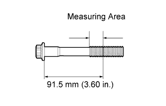 |
Using a vernier caliper, measure the thread outside diameter of the crankshaft bearing cap set bolt.