Home › BODY ELECTRICAL › AUDIO / VISUAL › AUDIO AND VISUAL SYSTEM

AUDIO AND VISUAL SYSTEM > Speed Signal Circuit

for Preparation Click here


DESCRIPTION

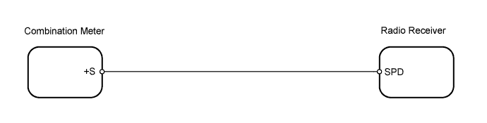
This circuit sends a speed signal from the combination meter to the radio receiver.

WIRING DIAGRAM


I102036E02


INSPECTION PROCEDURE

1.CHECK OPERATION OF SPEEDOMETER
  1. Drive the vehicle and check if the function of the speedometer on the combination meter is normal.

    OK:
    Actual speed and the speed indicated on the speedometer are the same.

    HINT:
    The vehicle speed sensor is functioning normally when the indication on the speedometer is normal.


NG
GO TO METER / GAUGE SYSTEM
OK


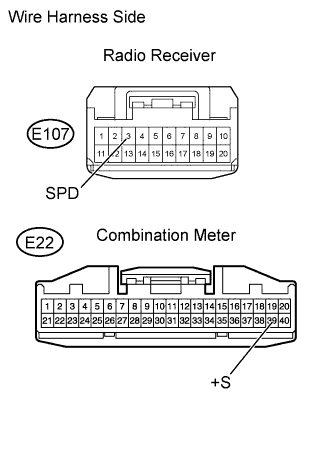
2.CHECK HARNESS AND CONNECTOR (RADIO RECEIVER - COMBINATION METER)


    E182348E02
  1. Disconnect the E107 radio receiver connector.

  1. Disconnect the E22 meter connector.

  1. Measure the resistance according to the value(s) in the table below.

    Standard Resistance:
    Tester Connection
    Specified Condition
    E107-3 (SPD) - E22-39 (+S)
    Below 1 Ω


NG
REPAIR OR REPLACE HARNESS OR CONNECTOR
OK

REPLACE RADIO RECEIVER ASSEMBLY