FRONT DRIVE SHAFT ASSEMBLY (for 4WD) > INSTALLATION |
| 1. INSTALL FRONT DRIVE SHAFT ASSEMBLY LH |
|
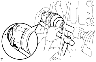
Coat the splines of the inboard joint shaft with gear oil.
Align the shaft splines and tap in the drive shaft with a brass bar and hammer.
| 2. INSTALL FRONT DRIVE SHAFT ASSEMBLY RH |
Coat the splines of the inboard joint shaft with gear oil.
Align the shaft splines and securely insert the drive shaft.
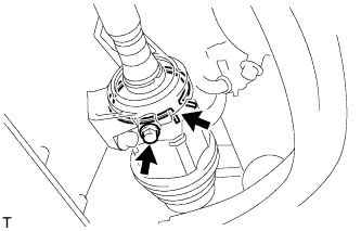 |
Squeeze the ends of the snap ring and install it to the bearing bracket.
Install a new bearing bracket bolt.
| 3. CONNECT STEERING KNUCKLE WITH AXLE HUB LH |
Align the matchmarks and connect the steering knuckle with axle hub.
| 4. CONNECT STEERING KNUCKLE WITH AXLE HUB RH |
| 5. CONNECT FRONT SUSPENSION LOWER NO. 1 ARM SUB-ASSEMBLY LH |
Connect the lower arm to the ball joint with the 2 bolts and nut.
| 6. CONNECT FRONT SUSPENSION LOWER NO. 1 ARM SUB-ASSEMBLY RH |
| 7. INSTALL FRONT STABILIZER LINK ASSEMBLY LH |
Install the link with the 2 nuts.
| 8. INSTALL FRONT STABILIZER LINK ASSEMBLY RH |
| 9. CONNECT TIE ROD END SUB-ASSEMBLY LH |
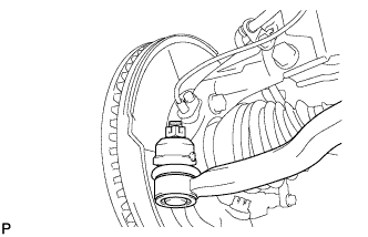 |
Connect the tie rod end onto the steering knuckle with the castle nut.
Install a new cotter pin.
| 10. CONNECT TIE ROD END SUB-ASSEMBLY RH |
| 11. CONNECT FRONT DISC BRAKE CYLINDER ASSEMBLY LH |
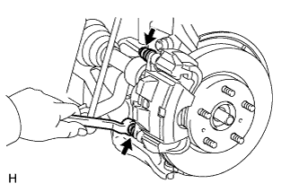 |
Install the cylinder with the 2 bolts.
| 12. CONNECT FRONT DISC BRAKE CYLINDER ASSEMBLY RH |
| 13. INSTALL FRONT SPEED SENSOR LH |
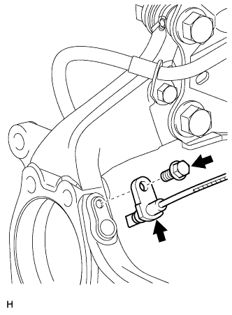 |
Set the sensor body into the knuckle, and then install the sensor with the bolt.
Install the sensor clamp and sensor clip as follows.
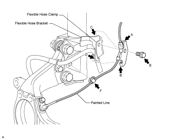
Simultaneously perform the following: 1) hang the hook part of the sensor clamp (labeled A) on the part of the flexible hose bracket (labeled C); and 2) insert the hook part of the sensor clamp (labeled B) to the part of the flexible hose bracket (labeled D).
Install the sensor clamp to the flexible hose clamp and flexible hose bracket with the bolt (labeled E).
Insert the sensor clip (labeled F) into the hole on the absorber lower bracket.
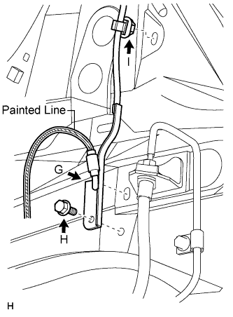 |
Install the sensor clamp and sensor clip as follows.
Set the sensor clamp (labeled G) on the side member, and then install the bolt (labeled H).
Insert the sensor clip (labeled I) into the hole on the apron.
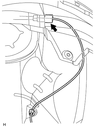 |
Connect the sensor connector.
| 14. INSTALL FRONT SPEED SENSOR RH |
| 15. INSTALL FRONT AXLE HUB NUT |
Clean the threaded parts on the drive shaft and axle hub nut using a non-residue solvent.
Install a new hub nut.
Using a chisel and hammer, stake the hub nut.
| 16. INSTALL FRONT WHEEL |
| 17. ADD AUTOMATIC TRANSAXLE FLUID |
| 18. ADD TRANSAXLE OIL |
| 19. INSPECT FOR OIL LEAK |
| 20. INSPECT AND ADJUST FRONT WHEEL ALIGNMENT |
Inspect and adjust the front wheel alignment (Click here).