 |
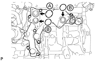
Apply engine oil to 2 new O-rings labeled B in the illustration.
- NOTICE:
- Do not apply engine oil to the new O-ring labeled A in the illustration.
ENGINE OIL COOLER > INSTALLATION |
| 1. INSTALL OIL COOLER ASSEMBLY |
|
Apply engine oil to 2 new O-rings labeled B in the illustration.
Install 3 new O-rings to the oil cooler bracket.
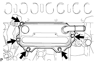 |
Install the oil cooler with the 5 bolts.
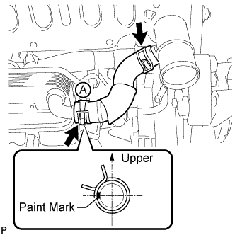
| 2. INSTALL NO. 1 WATER BY-PASS HOSE |
 |
| 3. INSTALL INTAKE MANIFOLD |
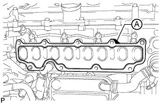 |
Install a new gasket to the cylinder head.
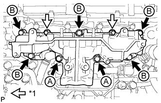 |
Install the intake manifold with the 7 bolts and 2 nuts.
| *1 | Nut |
| Item | Length |
| Bolt A | 90 mm (3.54 in.) |
| Bolt B | 25 mm (0.984 in.) |
| 4. CONNECT NO. 2 VACUUM TRANSMITTING HOSE |
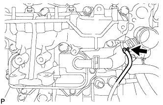 |
Connect the No. 2 vacuum transmitting hose to the intake manifold.
| 5. INSTALL NO. 2 INTAKE MANIFOLD |
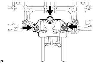 |
Install a new gasket and the No. 2 intake manifold with the bolt and 2 nuts.
| 6. INSTALL ENGINE COVER BRACKET |
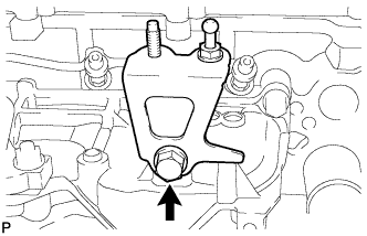 |
Install the engine cover bracket with the bolt.
| 7. INSTALL GAS FILTER BRACKET |
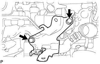 |
Install the gas filter bracket with the 2 bolts.
| 8. INSTALL NO. 1 GAS FILTER |
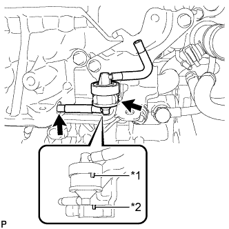 |
Install the No. 1 gas filter to the gas filter bracket.
| *1 | Protrusion |
| *2 | Groove |
Connect the vacuum hose.
| 9. INSTALL DIESEL TURBO PRESSURE SENSOR |
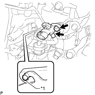 |
Install the sensor with the bolt.
| *1 | Protrusion |
Connect the vacuum hose.
| 10. INSTALL ENGINE OIL LEVEL DIPSTICK GUIDE |
Install a new O-ring to the engine oil level dipstick guide.
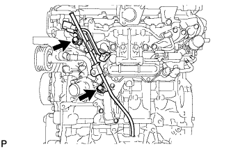 |
Install the engine oil level dipstick guide with the 2 bolts.
Install the engine oil level dipstick.
| 11. INSTALL INTAKE MANIFOLD INSULATOR |
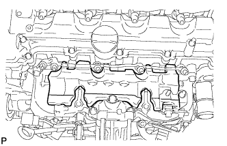 |
Install the intake manifold insulator to the intake manifold.
| 12. INSTALL COMMON RAIL ASSEMBLY |
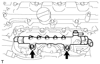 |
Install the common rail with the 2 bolts.
| 13. INSTALL INJECTION PIPE SUB-ASSEMBLY |
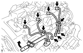 |
Using a 14 mm union nut wrench, tighten the 4 nuts at the common rail end of the injection pipes.
Using a 14 mm union nut wrench, tighten the 4 nuts at the injector end of the injection pipes.
Install the 4 injection pipe clamps with the 2 bolts.
| 14. INSTALL FUEL INLET PIPE SUB-ASSEMBLY |
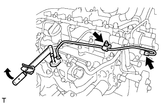 |
Temporarily install the fuel inlet pipe with the 2 clamps and nut.
Using a 14 mm union nut wrench, first tighten the nut at the common rail end of the fuel inlet pipe.
Using a 14 mm union nut wrench, tighten the nut at the supply pump end of the fuel inlet pipe.
Tighten the No. 2 injection pipe clamp nut.
| 15. INSTALL ELECTRIC EGR CONTROL VALVE ASSEMBLY |
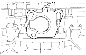 |
Install a new gasket.
| *1 | Protrusion |
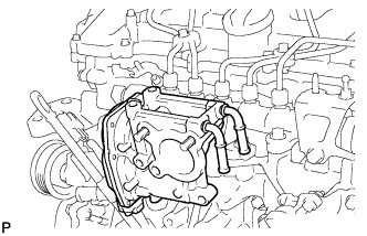 |
Install the electric EGR control valve.
| 16. INSTALL NO. 2 EGR PIPE SUB-ASSEMBLY |
Install a new gasket to the electric EGR control valve.
Install a new gasket to the No. 2 EGR pipe.
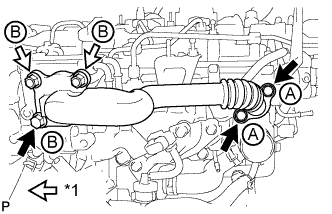 |
Temporarily install the No. 2 EGR pipe with the 3 bolts and 2 nuts.
| *1 | Nut |
| Item | Length |
| Bolt A | 25 mm (0.984 in.) |
| Bolt B | 70 mm (2.76 in.) |
Tighten the 2 bolts labeled A shown in the illustration.
Tighten the bolt and 2 nuts labeled B shown in the illustration.
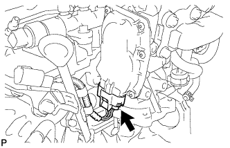 |
Connect the electric EGR control valve connector.
| 17. CONNECT NO. 8 WATER BY-PASS HOSE |
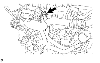 |
| 18. INSTALL NO. 7 WATER BY-PASS HOSE |
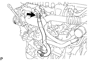 |
| 19. INSTALL EGR VALVE BRACKET |
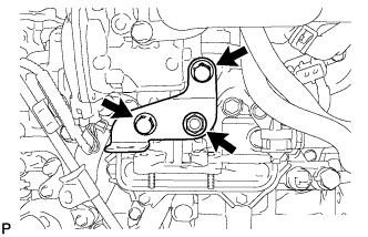 |
Install the EGR valve brackets with the 3 bolt.
| 20. CONNECT ENGINE WIRE |
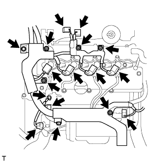 |
Connect the engine wire to the engine cover bracket with the bolt and 5 nuts.
Connect the engine wire to the wire bracket with the bolt.
Connect the pressure discharge valve connector.
Connect the emission control valve wire connector.
Connect the fuel pressure sensor connector.
Connect the glow plug wire harness with the nut and grommet.
Connect the 4 injector connectors.
Connect the vacuum switching valve connector.
Connect the vacuum regulating valve connector.
| 21. INSTALL DIESEL THROTTLE BODY ASSEMBLY |
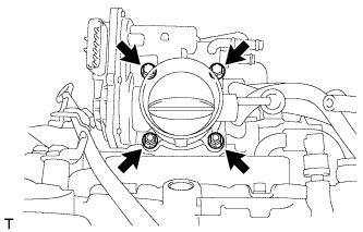 |
Install a new gasket and the diesel throttle body with the 2 bolts and 2 nuts.
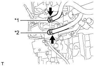 |
Connect the No. 6 and No. 7 water by-pass hoses.
| *1 | No. 6 Water By-pass Hose |
| *2 | No. 7 Water By-pass Hose |
| 22. INSTALL NO. 3 AIR HOSE |
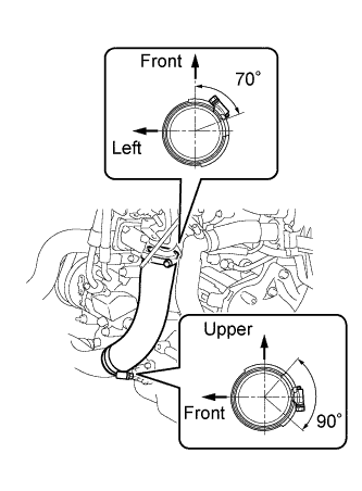 |
Install the No. 3 air hose to the No. 2 air tube and throttle body.
Tighten the 2 hose clamps as shown in the illustration.
| 23. ADD ENGINE OIL |
Add new engine oil.
| Item | Oil Grade | Oil Viscosity (SAE) |
| for CCo: Diesel fuel that contains between 50 ppm and 500 ppm of sulfur | ACEA B1, API CF-4 or CF (You may also use API CE or CD) | - 5W-30 - 10W-30 - 15W-40 - 20W-50 |
| for CCo: Diesel fuel that contains 50 ppm or less of sulfur | ACEA C2, B1, API CF-4 or CF (You may also use API CE or CD) | - 0W-30 - 5W-30 - 10W-30 - 15W-40 - 20W-50 |
| for DPF | ACEA C2 | - 0W-30 - 5W-30 |
| Item | Specified Condition |
| Drain and refill without oil filter change | 5.5 liters (5.8 US qts, 4.8 Imp. qts) |
| Drain and refill with oil filter change | 5.9 liters (6.2 US qts, 5.2 Imp. qts) |
| Dry fill | 6.7 liters (7.1 US qts, 5.9 Imp. qts) |
| 24. CONNECT CABLE TO NEGATIVE BATTERY TERMINAL |
| 25. BLEED AIR FROM FUEL SYSTEM |
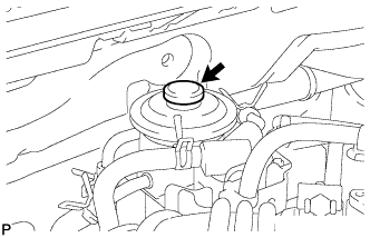 |
Using the hand pump mounted on the fuel filter cap, bleed the air from the fuel system. Continue pumping until the pump resistance increases.
Start the engine.
When the engine can be started, proceed to the next step.
If the engine cannot be started, bleed the air again using the hand pump until the hand pump resistance increases (refer to the procedures above). Then start the engine.
Turn the ignition switch off.
Connect the intelligent tester to the DLC3.
Turn the ignition switch to ON and turn the intelligent tester on.
Clear DTCs (Click here).
Start the engine.*1
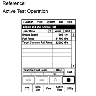 |
Enter the following menus: Powertrain / Engine and ECT / Active Test / Test the Fuel Leak.*2
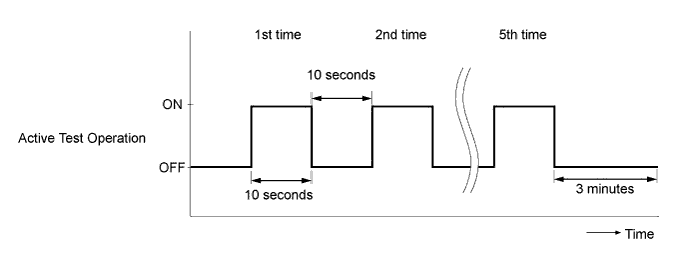
Perform the following test 5 times with on/off intervals of 10 seconds: Active Test / Test the Fuel Leak.*3
Allow the engine to idle for 3 minutes or more after performing the Active Test for the fifth time.
Enter the following menus: Powertrain / Engine and ECT / DTC.
Read Current DTCs.
When no DTCs are output, the air bleeding is completed.
If any DTCs are output, proceed to the next step.
Clear the DTCs (Click here).
Repeat steps *1 to *3.
Enter the following menus: Powertrain / Engine and ECT / DTC.
Read Current DTCs.
| 26. ADD ENGINE COOLANT |
Tighten the radiator drain cock plug by hand.
Tighten the cylinder block drain cock plug.
Add TOYOTA Super Long Life Coolant (SLLC) to the radiator reservoir filler opening.
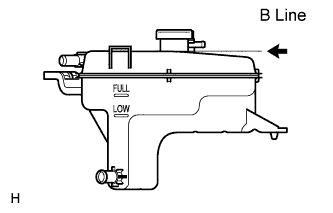 |
Continue adding TOYOTA SLLC until it is filled to the B line.
| Item | Specified Condition |
| w/o Combustion Type Power Heater | 7.3 liters (7.7 US qts, 6.4 Imp. qts) |
| w/ Combustion Type Power Heater | 7.7 liters (8.1 US qts, 6.8 Imp. qts) |
Press the inlet and outlet radiator hoses several times by hand, and then check the level of the coolant.
If the coolant level drops below the B line, add TOYOTA SLLC to the B line.
Install the radiator reservoir cap.
Start the engine, and warm it up until the cooling fan operates.
Set the air conditioning as follows while warming up the engine.
| Item | Condition |
| Manual Air Conditioning System | Fan speed - Any setting except "OFF" |
| Temperature - Toward WARM Air conditioning switch "OFF" | |
| Automatic Air Conditioning System | Temperature - Toward MAX Air conditioning switch "OFF" |
Maintain the engine speed at 2000 to 2500 rpm and warm up the engine until the cooling fan operates.
Press the inlet and outlet radiator hoses several times by hand to bleed air.
Stop the engine and wait until the coolant cools down to ambient temperature.
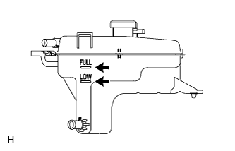 |
Check that the coolant level is between the FULL and LOW line.
If the coolant level is below the LOW line, repeat all of the procedures above.
If the coolant level is above the FULL line, drain coolant so that the coolant level is between the FULL and LOW line.
| 27. INSPECT FOR COOLANT LEAK |
Remove the radiator reservoir cap.
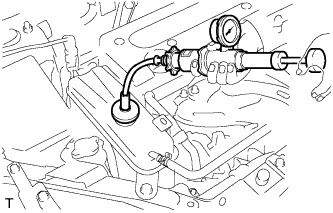 |
Fill the radiator with coolant, and then attach a radiator cap tester.
Warm up the engine.
Pump the radiator cap tester to 118 kPa (1.2 kgf/cm2, 17 psi), and then check that the pressure does not drop.
If the pressure drops, check the hoses, radiator and water pump for leakage.
If there are no signs of external coolant leaks, check the heater core, cylinder block and head.
Reinstall the radiator cap.
| 28. INSPECT FOR OIL LEAK |
Warm up the engine and check for an engine oil leak.
| 29. INSPECT FOR FUEL LEAK |
Perform Active Test.
Connect the intelligent tester to the DLC3.
Turn the ignition switch to ON.
Start the engine.
Turn the intelligent tester on.
Enter the following menus: Powertrain / Engine and ECT / Active Test.
Perform the Active Test.
| Tester Display | Test Part | Control Range | Diagnostic Notes |
| Test the Fuel Leak | Pressurizes common rail internal fuel pressure, and checks for fuel leaks | Stop/Start | Performs inspection of the high pressure fuel system.
|
| 30. INSPECT ENGINE OIL LEVEL |
Warm up the engine, stop the engine and wait 5 minutes. The engine oil level should be between the dipstick low level mark and full level mark.
If low, check for leakage and add oil up to the full level mark.
| 31. INSTALL NO. 1 ENGINE UNDER COVER |
Install the engine under cover with the 6 bolts and 10 clips.
| 32. INSTALL RADIATOR SUPPORT OPENING COVER |
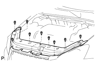 |
Install the radiator support opening cover with the 9 clips.
| 33. INSTALL NO. 1 ENGINE COVER |
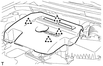 |
Attach the 4 clips to install the engine cover.