Home › ENGINE ยท 2AD-FHV › EMISSION CONTROL › EXHAUST GAS TEMPERATURE SENSOR

EXHAUST GAS TEMPERATURE SENSOR > INSTALLATION

for Preparation Click here


1. INSTALL EXHAUST GAS TEMPERATURE SENSOR (for Upper Side)

NOTICE:
If the sensor is dropped, replace it with a new one.


    A201864
  1. Using a 14 mm union nut wrench, install the sensor.

    Torque:
    30 N*m{ 306 kgf*cm , 22 ft.*lbf }

    NOTICE:
    Use the formula to calculate special torque values for situations where a union nut wrench is combined with a torque wrench (Click here).

  1. Attach the sensor connector clamp.


2. INSTALL EXHAUST GAS TEMPERATURE SENSOR (for Lower Side)

NOTICE:
If the sensor is dropped, replace it with a new one.


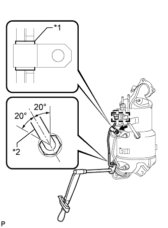
    A206305E01
  1. Temporarily install the sensor with the union nut.
    Text in Illustration 
    *1
    White Tube
    *2
    Protection Tube

  1. Attach the sensor connector clamp.

  1. Temporarily install the clamp with the nut.

    NOTICE:
    Make sure the clamp is aligned with the white tube of the wire harness as shown in the illustration.

  1. Tighten the nut.

    Torque:
    6.4 N*m{ 65 kgf*cm , 57 in.*lbf }

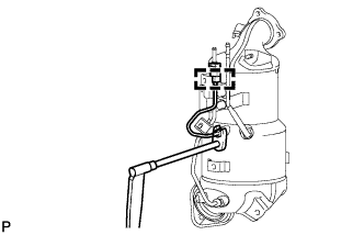
  1. Using a 14 mm union nut wrench, tighten the union nut of the sensor.

    Torque:
    30 N*m{ 306 kgf*cm , 22 ft.*lbf }

    NOTICE:
    1. When tightening the union nut, make sure that the protection tube of the sensor is within the range shown in the illustration.
    2. Use the formula to calculate special torque values for situations where a union nut wrench is combined with a torque wrench (Click here).


3. INSTALL EXHAUST MANIFOLD CONVERTER SUB-ASSEMBLY


  1. Install a new gasket to the turbocharger.
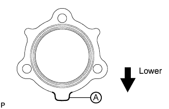
    HINT:
    A206476E01
    Make sure that the part labeled A is facing downwards as shown in the illustration.


    A197484
  1. Temporarily install the exhaust manifold converter with the 3 nuts.


    A197482
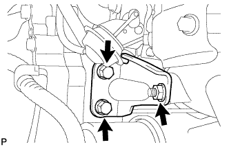
  1. Temporarily install the No. 2 exhaust manifold stay with the 2 bolts and nut.


    A197481
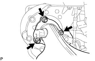
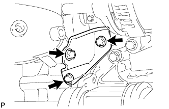
  1. Temporarily install the No. 2 manifold stay with the 3 bolts.


    A197483
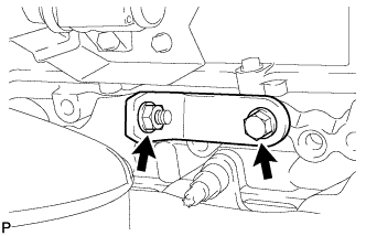
  1. Temporarily install the manifold stay with the bolt and nut.


    A201848E01
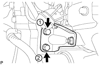
  1. Tighten the 2 bolts of the No. 2 exhaust manifold stay in the order shown in the illustration.

    Torque:
    56 N*m{ 571 kgf*cm , 41 ft.*lbf }


    A197484
  1. Tighten the 3 nuts of the exhaust manifold converter.
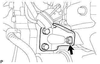
    Torque:
    25 N*m{ 255 kgf*cm , 18 ft.*lbf }

    NOTICE:
    Tighten the nuts while pressing the exhaust manifold converter against the engine.


    A201849
  1. Tighten the nut of the No. 2 exhaust manifold stay.
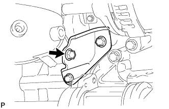
    Torque:
    56 N*m{ 571 kgf*cm , 41 ft.*lbf }


    A201845
  1. Tighten the bolt of the No. 2 manifold stay shown in the illustration.
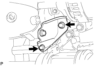
    Torque:
    56 N*m{ 571 kgf*cm , 41 ft.*lbf }

    NOTICE:
    Tighten the bolt while pressing the No. 2 manifold stay against the exhaust manifold converter and cylinder block.


    A201846
  1. Tighten the 2 bolts of the No. 2 manifold stay shown in the illustration.
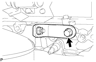
    Torque:
    56 N*m{ 571 kgf*cm , 41 ft.*lbf }


    A201850
  1. Tighten the bolt of the manifold stay.
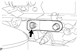
    Torque:
    25 N*m{ 255 kgf*cm , 18 ft.*lbf }

    NOTICE:
    Tighten the bolt while pressing the manifold stay against the exhaust manifold converter and cylinder block.


    A201851
  1. Tighten the nut of the manifold stay.

    Torque:
    25 N*m{ 255 kgf*cm , 18 ft.*lbf }


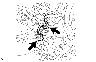
    A206298
  1. Connect the 2 connectors.


4. INSTALL NO. 1 MANIFOLD CONVERTER INSULATOR


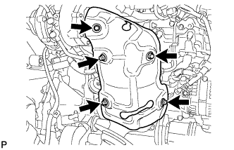
    A197480
  1. Install the insulator with the 5 bolts.

    Torque:
    29 N*m{ 291 kgf*cm , 21 ft.*lbf }


5. INSTALL ENGINE ASSEMBLY
  1. Install the engine assembly (Click here).