 |
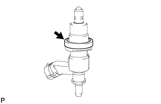
Install a new fuel injector seal to the exhaust fuel addition injector.
EXHAUST FUEL ADDITION INJECTOR > INSTALLATION |
| 1. INSTALL FUEL INJECTOR SEAL |
|
Install a new fuel injector seal to the exhaust fuel addition injector.
| 2. INSTALL EXHAUST FUEL ADDITION INJECTOR ASSEMBLY |
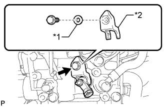 |
Install a new gasket, the exhaust fuel addition injector and nozzle holder clamp with the washer and bolt.
| *1 | Washer |
| *2 | Nozzle Holder Clamp |
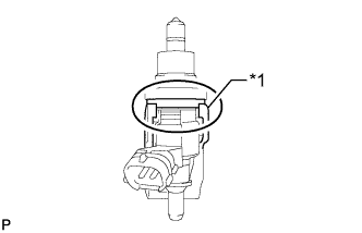 |
| *1 | Nozzle Holder Clamp |
| 3. INSTALL FUEL TUBE SUB-ASSEMBLY |
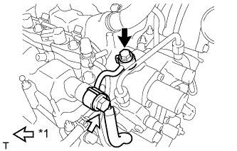 |
Temporarily install the fuel tube with 2 new gaskets, the check valve and union bolt.
| *1 | Check Valve |
Tighten the check valve.
Tighten the union bolt.
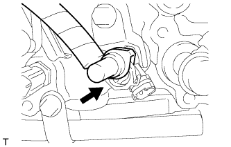 |
Insert the fuel tube connector onto the injector.
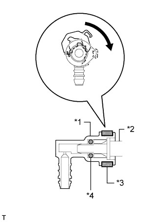 |
Turn the retainer in the direction indicated by the arrow until it makes a "click" sound.
| *1 | Fuel Tube Connector |
| *2 | Injector |
| *3 | Retainer |
| *4 | O-Ring |
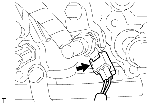 |
Connect the exhaust fuel addition injector connector.
| 4. INSTALL FUEL HOSE PROTECTOR |
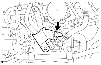 |
Install the fuel hose protector with the bolt.
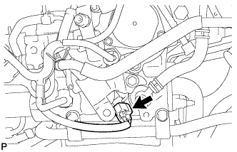 |
Connect the connector.
| 5. INSTALL AIR CLEANER CASE SUB-ASSEMBLY |
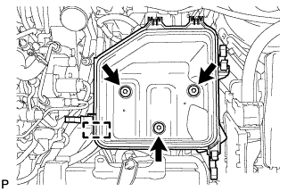 |
Attach the clamp and install the air cleaner case with the 3 bolts.
| 6. INSTALL AIR CLEANER FILTER ELEMENT SUB-ASSEMBLY |
| 7. INSTALL AIR CLEANER CAP SUB-ASSEMBLY |
Connect the air cleaner hose.
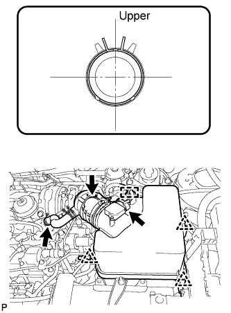 |
Attach the 3 clips to install the air cleaner cap.
Connect the PCV hose.
Attach the clamp and connect the mass air flow meter connector.
| 8. CONNECT CABLE TO NEGATIVE BATTERY TERMINAL |
| 9. INSPECT FOR FUEL LEAK |
Perform Active Test.
Connect the intelligent tester to the DLC3.
Turn the ignition switch to ON.
Start the engine.
Turn the intelligent tester on.
Enter the following menus: Powertrain / Engine and ECT / Active Test.
Perform the Active Test.
| Tester Display | Test Part | Control Range | Diagnostic Notes |
| Test the Fuel Leak | Pressurizes common rail internal fuel pressure, and checks for fuel leaks | Stop/Start | Performs inspection of the high pressure fuel system.
|
| 10. INSTALL NO. 1 ENGINE COVER |
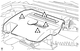 |
Attach the 4 clips to install the engine cover.