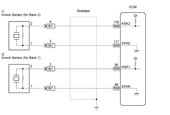
DTC P0327 Knock Sensor 1 Circuit Low Input (Bank 1 or Single Sensor) |
DTC P0328 Knock Sensor 1 Circuit High Input (Bank 1 or Single Sensor) |
DTC P0332 Knock Sensor 2 Circuit Low Input (Bank 2) |
DTC P0333 Knock Sensor 2 Circuit High Input (Bank 2) |
| DTC No. | DTC Detection Condition | Trouble Area |
| P0327 P0332 | Output voltage of knock sensor 1 or 2 is 0.5 V or less (1 trip detection logic) |
|
| P0328 P0333 | Output voltage of knock sensor 1 or 2 is 4.5 V or more (1 trip detection logic) |
|
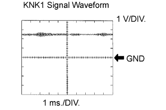
| Item | Content |
| Terminal | KNK1 - EKNK or KNK2 -EKN2 |
| Equipment Setting | 0.01 to 10 V/DIV. 0.01 to 10 ms./DIV. |
| Condition | Keep engine speed at 4000 rpm with warm engine |
| 1.READ OUTPUT DTC (CHECK KNOCK SENSOR CIRCUIT) |
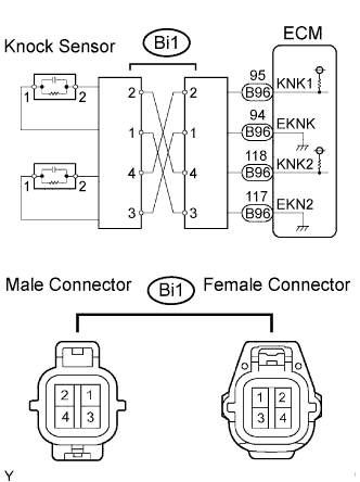 |
Disconnect the connector.
Using lead wires, connect the connectors as follows:
| Male Connector - Female Connector |
| Terminal 2 - Terminal 4 |
| Terminal 1 - Terminal 3 |
| Terminal 4 - Terminal 2 |
| Terminal 3 - Terminal 1 |
Warm up the engine.
Run the engine at 3000 rpm for 10 seconds or more.
Connect the intelligent tester to the DLC3.
Turn the ignition switch to the ON position and turn the intelligent tester on.
Enter the following menus: Powertrain / Engine and ECT / DTC.
Read the DTCs.
| Display | Proceed to |
| DTCs same as when vehicle brought in P0327, P0328 → P0327, P0328 or P0332, P0333 → P0332, P0333 | A |
| DTCs different from when vehicle brought in P0327, P0328 → P0332, P0333 or P0332, P0333 → P0327, P0328 | B |
Reconnect the connector.
|
| ||||
| A | |
 |
| 2.CHECK WIRE HARNESS AND CONNECTOR (CONNECTOR - ECM) |
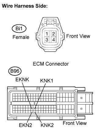 |
Disconnect the connector.
Disconnect the ECM connector.
Measure the resistance according to the value(s) in the table below.
| Tester Connection | Specified Condition |
| Bi1 female connector 2 - KNK1 (B96-95) | Below 1 Ω |
| Bi1 female connector 1 - EKNK (B96-94) | Below 1 Ω |
| Tester Connection | Specified Condition |
| Bi1 female connector 4 - KNK2 (B96-118) | Below 1 Ω |
| Bi1 female connector 3 - EKN2 (B96-117) | Below 1 Ω |
| Tester Connection | Specified Condition |
| Bi1 female connector 2 or KNK1 (B96-95) - Body ground | 10 kΩ or higher |
| Bi1 female connector 1 or EKNK (B96-94) - Body ground | 10 kΩ or higher |
| Tester Connection | Specified Condition |
| Bi1 female connector 4 or KNK2 (B96-118) - Body ground | 10 kΩ or higher |
| Bi1 female connector 3 or EKN2 (B96-117) - Body ground | 10 kΩ or higher |
Reconnect the connector.
Reconnect the ECM connector.
|
| ||||
| OK | |
|
| 3.INSPECT ECM |
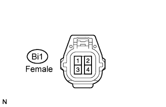 |
Disconnect the connector.
Turn the ignition switch to the ON position.
Measure the voltage according to the value(s) in the table below.
| Tester Connection | Specified Condition |
| Bi1 female connector 2 - 1 | 4.5 to 5.5 V |
| Bi1 female connector 4 - 3 | 4.5 to 5.5 V |
Reconnect the ECM connector.
|
| ||||
| OK | ||
 | ||
| ||
| 4.INSPECT KNOCK SENSOR |
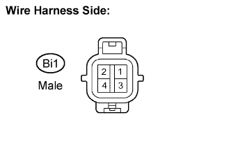 |
Disconnect the connector.
Measure the resistance according to the value(s) in the table below.
| Tester Connection | Specified Condition |
| Bi1 male connector 1 - 2 | 120 to 280 kΩ |
| Bi1 male connector 3- 4 | 120 to 280 kΩ |
Reconnect the connector.
|
| ||||
| NG | |
|
| 5.CHECK HARNESS AND CONNECTOR (CONNECTOR - KNOCK SENSOR) |
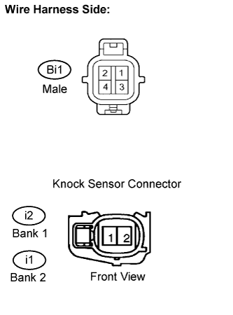 |
Disconnect the connector.
Disconnect the knock sensor connectors.
Measure the resistance according to the value(s) in the table below.
| Tester Connection | Specified Condition |
| Bi1 male connector 2 - i2-2 | Below 1 Ω |
| Bi1 male connector 1 - i2-1 | Below 1 Ω |
| Tester Connection | Specified Condition |
| Bi1 male connector 4 - i1-2 | Below 1 Ω |
| Bi1 male connector 3 - i1-1 | Below 1 Ω |
| Tester Connection | Specified Condition |
| Bi1 male connector 2 or i2-2 - Body ground | 10 kΩ or higher |
| Bi1 male connector 1 or i2-1 - Body ground | 10 kΩ or higher |
| Tester Connection | Specified Condition |
| Bi1 male connector 4 or i1-2 - Body ground | 10 kΩ or higher |
| Bi1 male connector 3 or i1-1 - Body ground | 10 kΩ or higher |
Reconnect the connector.
Reconnect the knock sensor connectors.
|
| ||||
| OK | ||
| ||
| ||

