 |
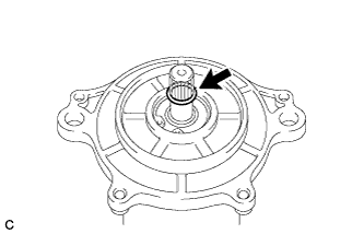
Install a new O-ring to the power steering motor assembly.
STEERING COLUMN ASSEMBLY (for RHD) > REASSEMBLY |
| 1. INSTALL POWER STEERING MOTOR ASSEMBLY |
|
Install a new O-ring to the power steering motor assembly.
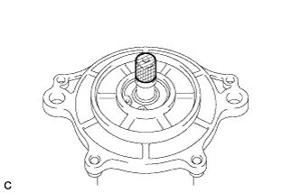 |
Apply grease to the serrated part of the power steering motor assembly.
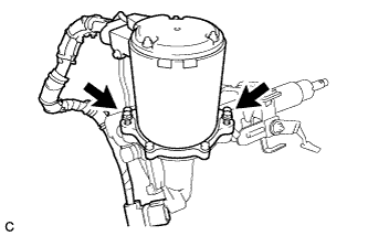 |
Temporarily install the power steering motor assembly to the electric power steering column sub-assembly with the 2 bolts.
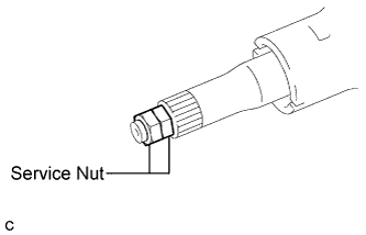 |
Install the 2 service nuts to the steering main shaft.
Rotate the 2 installed service nuts simultaneously to lock them: rotate the one installed first counter clockwise and rotate the one installed second clockwise.
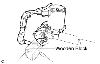 |
Secure the steering column assembly in a vice using aluminum plates or a piece of cloth as shown in the illustration.
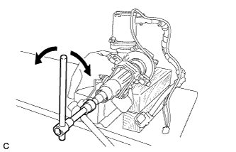 |
Turn the steering main shaft once 180 degrees to the left and then 180 degrees to the right at a speed of 60 rpm, and repeat 2 to 3 times to adjust the axis of the power steering motor assembly.
Remove the steering column assembly from the vice.
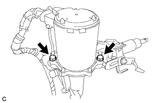 |
Tighten the 2 bolts.
|
Secure the steering column assembly in a vice using aluminum plates or a piece of cloth as shown in the illustration.
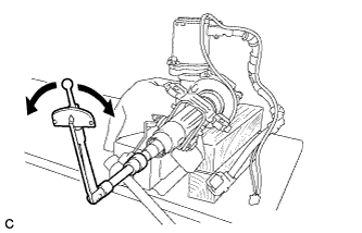 |
Measure the turning torque of the steering main shaft.
Remove the 2 service nuts from the steering main shaft.
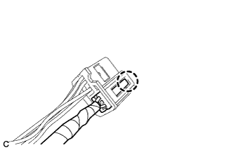 |
Engage the claw to install the torque sensor harness connector.
Apply tape to the wire harness as shown in the illustration.
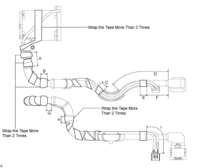
| A | 40 mm (1.57 in.) |
| B | 30 mm (1.18 in.) |
| C | 30 mm (1.18 in.) |
| D | 145 to 155 mm (5.71 to 6.10 in.) |
| E | 30 mm (1.18 in.) |
| F | 55 to 65 mm (2.17 to 2.56 in.) |
| G | 10 to 20 mm (0.394 to 0.787 in.) |
| H | 30 mm (1.18 in.) |
| I | 95 to 105 mm (3.74 to 4.13 in.) |
| 2. INSTALL IGNITION SWITCH ASSEMBLY (w/o Entry and Start System) |
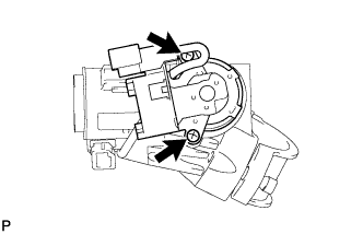 |
Install the ignition switch to the steering column bracket upper with the 2 screws.
| 3. INSTALL KEY INTERLOCK SOLENOID (w/o Entry and Start System) |
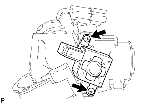 |
for Automatic Transaxle:
Install the key interlock solenoid to the steering column bracket assembly upper with the 2 screws.
| 4. INSTALL UNLOCK WARNING SWITCH ASSEMBLY (w/o Entry and Start System) |
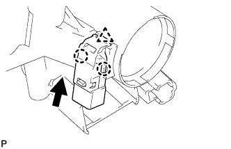 |
Attach the clip and 2 claws to install the unlock warning switch to the steering column bracket upper.
| 5. INSTALL IGNITION SWITCH LOCK CYLINDER ASSEMBLY (w/o Entry and Start System) |
Insert the key and turn it to the ACC position.
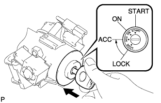 |
Install the ignition switch lock cylinder to the steering column bracket upper.
Make sure that the ignition switch lock cylinder is securely fixed to the steering column upper with switch bracket.
| 6. INSPECT STEERING LOCK OPERATION (w/o Entry and Start System) |
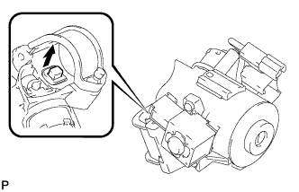 |
Remove the key and check that the steering lock function is activated.
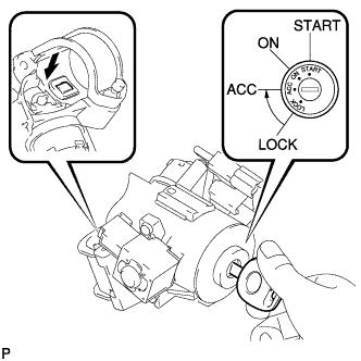 |
Insert the key, turn the ignition switch on (ACC) and check that the steering lock function is deactivated.
| 7. INSTALL STEERING COLUMN UPPER W/ SWITCH BRACKET ASSEMBLY (w/o Entry and Start System) |
Fix the steering column in a vise between aluminum plates.
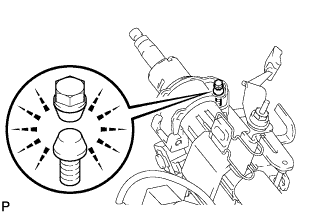 |
Install the steering column upper with switch bracket with a new steering lock set bolt, and then tighten the bolt until is head comes off.
| 8. INSTALL TRANSPONDER KEY AMPLIFIER (w/o Entry and Start System) |
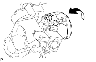 |
Attach the 2 claws and install the transponder key amplifier to the steering column upper with the switch bracket.
| 9. INSTALL STEERING LOCK ACTUATOR ASSEMBLY (w/ Entry and Start System) |
Fix the steering column in a vise between aluminum plates.
|
Install the steering lock actuator with a steering lock set bolt, and then tighten the bolts until their head comes off.