 |
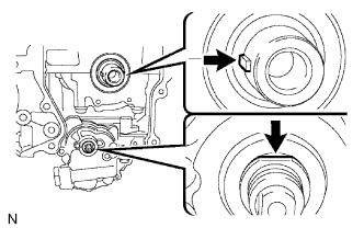
Set the crankshaft key in the left horizontal position.
TIMING CHAIN > INSTALLATION |
| 1. INSTALL NO. 2 CHAIN SUB-ASSEMBLY |
|
Set the crankshaft key in the left horizontal position.
Turn the cutout of the drive shaft so that it faces upward.
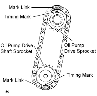 |
Align the yellow mark links with the timing marks of each gear as shown in the illustration.
Install the sprockets onto the crankshaft and oil pump shaft with the chain wrapped on the gears.
Temporarily tighten the oil pump drive shaft sprocket with the nut.
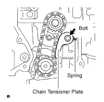 |
Insert the damper spring into the adjusting hole, and then install the chain tensioner plate with the bolt.
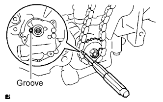 |
Align the adjusting hole of the oil pump drive shaft sprocket with the groove of the oil pump.
Insert a 4 mm diameter bar into the adjusting hole of the oil pump drive shaft gear to lock the gear in position, and then tighten the nut.
| 2. INSTALL CRANKSHAFT TIMING SPROCKET |
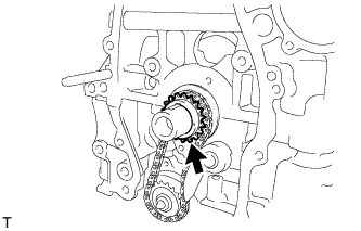 |
| 3. INSTALL NO. 1 CHAIN VIBRATION DAMPER |
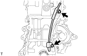 |
Install the chain vibration damper with the 2 bolts.
| 4. INSTALL CHAIN SUB-ASSEMBLY |
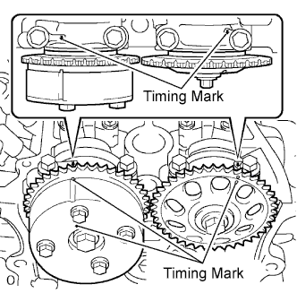 |
Set the No. 1 cylinder to TDC/compression.
Turn the camshafts with a wrench (using the hexagonal lobe) to align the timing marks of the camshaft timing gear with each timing mark located on the No. 1 and No. 2 bearing caps as shown in the illustration.
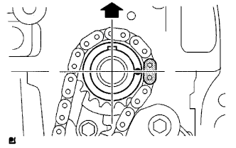 |
Using the crankshaft pulley bolt, turn the crankshaft to position the key on the crankshaft upward.
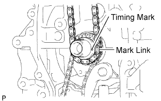 |
Install the chain onto the crankshaft timing sprocket with the gold or orange mark link aligned with the timing mark on the crankshaft.
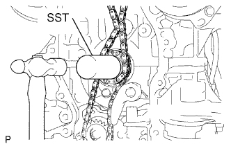 |
Using SST and a hammer, tap in the crankshaft timing sprocket.
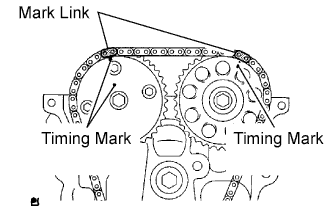 |
Align the gold or yellow links with each timing mark located on the camshaft timing gear and sprocket, then install the chain.
| 5. INSTALL CHAIN TENSIONER SLIPPER |
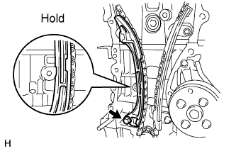 |
Install the chain tensioner slipper with the bolt.
| 6. INSTALL TIMING CHAIN GUIDE |
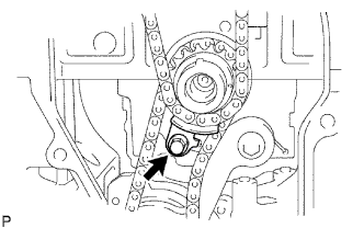 |
Install the timing chain guide with the bolt.
| 7. INSTALL NO. 1 CRANKSHAFT POSITION SENSOR PLATE |
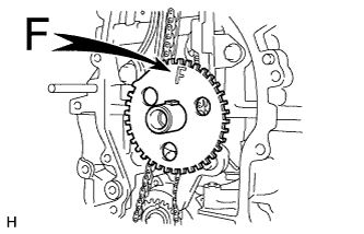 |
Install the sensor plate with the "F" mark facing forward.
| 8. INSTALL TIMING CHAIN COVER SUB-ASSEMBLY |
Remove any old packing material and be careful not to drop any oil on the contact surfaces of the timing chain cover, cylinder head and cylinder block.
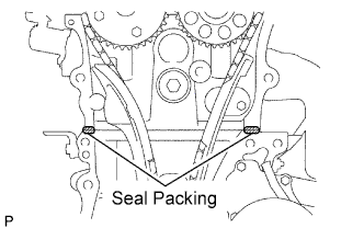 |
Apply seal packing (Diameter 4.0 to 4.5 mm (0.157 to 0.177 in.)) as shown in the illustration.
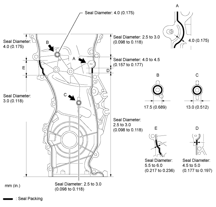
Apply a continuous bead of seal packing as shown in the illustration.
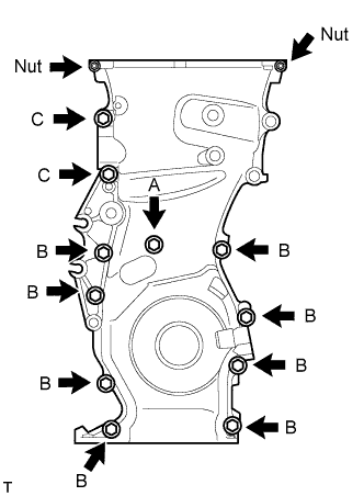 |
Install the timing chain cover with the 11 bolts and 2 nuts.
| Bolt A | 30 mm (1.18 in.) length for 10 mm head |
| Bolt B | 30 mm (1.18 in.) length for 12 mm head |
| Bolt C | 40 mm (1.57 in.) length for 14 mm head |
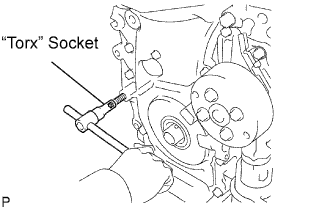 |
Using an E10 "torx" socket, install the stud bolt for the V-ribbed belt tensioner.
| 9. INSTALL NO. 1 CHAIN TENSIONER ASSEMBLY |
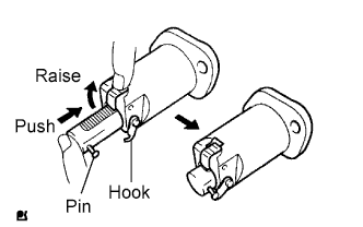 |
Release the ratchet pawl, then fully push in the plunger and hook the hook to the pin so that the plunger is in the position shown in the illustration.
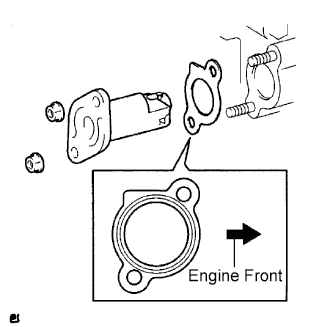 |
Install a new gasket and the chain tensioner with the 2 nuts.
| 10. INSTALL V-RIBBED BELT TENSIONER ASSEMBLY |
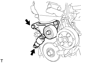 |
Install the V-ribbed belt tensioner with the bolt and nut.
| 11. INSTALL ENGINE MOUNTING BRACKET RH |
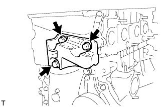 |
Install the engine mounting bracket RH with the 3 bolts.
| 12. INSTALL CRANKSHAFT PULLEY |
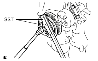 |
Using SST, fix the pulley in place and tighten the bolt.
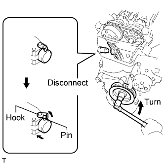 |
Turn the crankshaft counterclockwise, then disconnect the plunger knock pin from the hook.
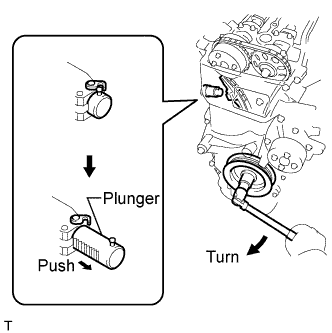 |
Turn the crankshaft clockwise, then check that the plunger is extended.
| 13. INSTALL OIL PAN SUB-ASSEMBLY |
Remove any old packing material and be careful not to drop any oil on the contact surfaces of the cylinder block and oil pan.
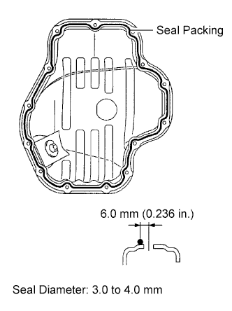 |
Apply a continuous bead of seal packing (Diameter 3.0 to 4.0 mm (0.118 to 0.157 in.)) as shown in the illustration.
Install the oil pan to the cylinder block.
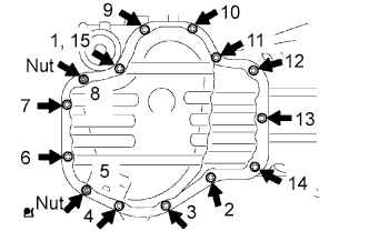 |
Uniformly tighten the 12 bolts and 2 nuts in the sequence shown in the illustration.
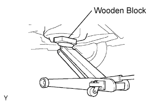 |
Place a transmission jack underneath the engine, then put a wooden block on the jack.
Remove the chain block and sling device.
Remove the No. 1 and No. 2 engine hangers.
| 14. INSTALL CRANKSHAFT POSITION SENSOR |
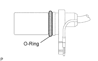 |
Apply a light coat of engine oil to the O-ring of the sensor.
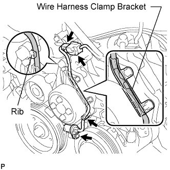 |
Install the sensor with the bolt.
Install the wire harness clamp.
Install the connector clamp.
Connect the sensor connector.
Confirm that the wire harness of the sensor is secured to the wire harness clamp bracket through the back of the rib of the timing chain cover.
| 15. INSTALL CYLINDER HEAD COVER SUB-ASSEMBLY |
Remove any old packing material from the contact surface.
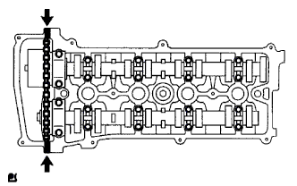 |
Apply seal packing to the 2 locations shown in the illustration.
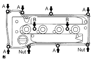 |
Install the cylinder head cover with the 8 bolts and 2 nuts.
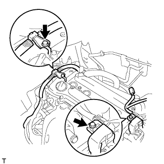 |
Install the 2 engine wires with the 2 bolts.
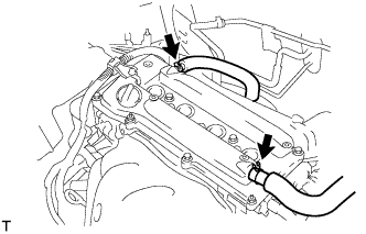 |
Connect the 2 ventilation hoses to the cylinder head cover.
| 16. INSTALL IGNITION COIL ASSEMBLY |
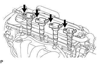 |
Install the 4 ignition coils with the 4 bolts.
Connect the 4 ignition coil connectors.
| 17. INSTALL IDLER PULLEY BRACKET |
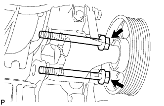 |
Install the bracket with the 2 bolts.
| 18. INSTALL ENGINE MOUNTING INSULATOR RH |
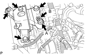 |
Install the engine mounting insulator RH with the 4 bolts and 2 nuts.
| 19. INSTALL ENGINE MOUNTING INSULATOR FR |
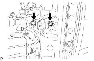 |
Install the engine mounting insulator FR with the 2 bolts.
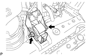 |
Install the bolt which is used to secure the front engine mounting bracket FR.
| 20. INSTALL RADIATOR RESERVOIR TANK |
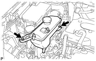 |
Install the radiator reservoir with the 2 bolts.
| 21. INSTALL GENERATOR ASSEMBLY |
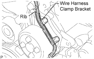 |
Confirm that the wire harness of the crankshaft position sensor is secured to the wire harness clamp bracket through the back of the rib of the timing chain cover.
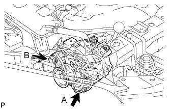 |
Install the generator with the 2 bolts.
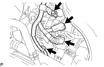 |
Install the wire harness clamp.
Install the wire harness clamp bracket with the bolt.
Connect the generator wire with the nut.
Install the terminal cap.
Connect the generator connector.
| 22. INSTALL FAN AND GENERATOR V BELT |
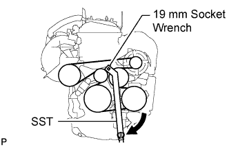 |
Using SST 19 mm socket wrench, loosen the V-ribbed belt tensioner arm clockwise, then install the fan and generator V belt.
| 23. INSTALL FRONT SUSPENSION MEMBER REINFORCEMENT RH |
Install the reinforcement RH with the 4 bolts.
| 24. INSTALL FRONT EXHAUST PIPE |
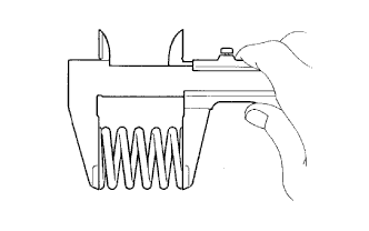 |
Using a vernier caliper, measure the free length of the compression spring.
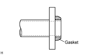 |
Install a new gasket by hand so that its surface is flush with the exhaust manifold.
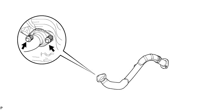
Install the front exhaust pipe with the 2 compression springs and 2 bolts.
| 25. ADD ENGINE OIL |
Clean and install the oil drain plug with a new gasket.
Add new oil.
| Item | Specified Condition |
| Drain and refill with oil filter change | 4.2 liters (4.4 US qts, 3.7 Imp. qts) |
| Drain and refill without oil filter change | 4.0 liters (4.2 US qts, 3.5 Imp. qts) |
| Dry fill | 4.9 liters (5.2 US qts, 4.3 Imp. qts) |
Install the oil filler cap.
| 26. CONNECT CABLE TO NEGATIVE BATTERY TERMINAL |
| 27. CHECK FOR ENGINE OIL LEAKS |
Start the engine, and check that there are no oil leaks.
| 28. CHECK FOR EXHAUST GAS LEAKS |
| 29. INSTALL NO. 1 ENGINE COVER |
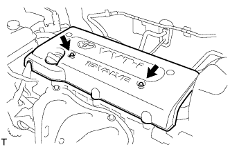 |
Install the engine cover with the 2 nuts.
| 30. INSTALL FRONT FENDER APRON RH |
| 31. INSTALL NO. 1 ENGINE UNDER COVER |
| 32. INSTALL FRONT WHEEL RH |
| 33. INSTALL RADIATOR SUPPORT OPENING COVER |