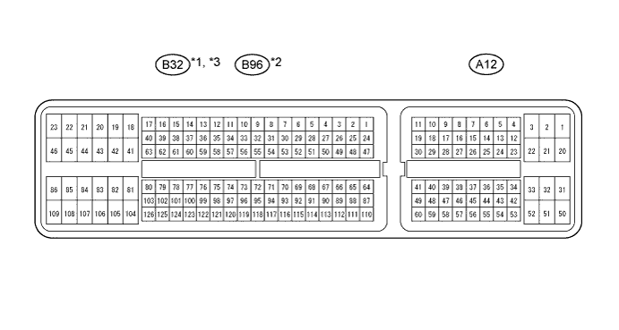
CRUISE CONTROL SYSTEM > TERMINALS OF ECM |
| CHECK ECM |
Disconnect the A12 and B32 or B96 connectors.
Measure the voltage and resistance of the wire harness side connectors.
| Symbols (Terminal No.) | Wiring Color | Terminal Description | Condition | Specified Condition |
| STP (A12-36) - E1 (B32-104)*1 STP (A12-36) - E1 (B96-81)*2 STP (A12-36) - E1 (B32-105)*3 | L - BR | Stop light switch input signal | Depress brake pedal | 11 to 14 V |
| Release brake pedal | Below 1 V | |||
| CCS (A12-40) - E1 (B32-104)*1 CCS (A12-40) - E1 (B96-81)*2 CCS (A12-40) - E1 (B32-105)*3 | L - BR | Cruise control main switch signal | CANCEL switch held ON | 1509 to 1571 Ω |
| -/SET switch held ON | 617 to 643 Ω | |||
| +/RES switch held ON | 235 to 245 Ω | |||
| Main switch OFF | 11 kΩ or higher | |||
| Main switch ON | Below 1 Ω | |||
| ST1- (A12-35) - E1 (B32-104)*1 ST1- (A12-35) - E1 (B96-81)*2 ST1- (A12-35) - E1 (B32-105)*3 | GR - BR | Stop light switch input signal | Release brake pedal | 11 to 14 V |
| Depress brake pedal | Below 1 V | |||
| D (B32-56) - E1 (B32-104)*1, *4 D (A12-47) - E1 (B32-105)*3, *4 | B - BR | Cruise control clutch switch input signal | Cruise control clutch switch is ON | 11 to 14 V |
| Cruise control clutch switch is OFF | Below 1 V |