 |
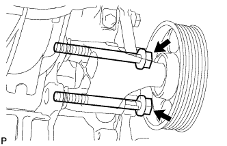
Loosen the 2 bolts and remove the bracket together with the 2 bolts.
ENGINE UNIT > DISASSEMBLY |
| 1. REMOVE IDLER PULLEY BRACKET |
|
Loosen the 2 bolts and remove the bracket together with the 2 bolts.
| 2. REMOVE OIL DIPSTICK |
| 3. REMOVE OIL DIPSTICK GUIDE |
Remove the bolt and guide.
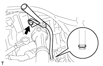 |
Remove the O-ring from the guide.
| 4. REMOVE MANIFOLD STAY |
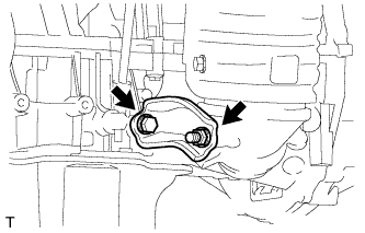 |
Remove the bolt, nut and stay.
| 5. REMOVE NO. 2 MANIFOLD STAY |
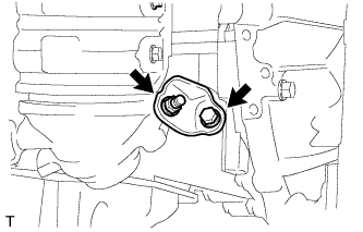 |
Remove the bolt, nut and stay.
| 6. REMOVE NO. 1 EXHAUST MANIFOLD HEAT INSULATOR |
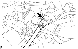 |
Disconnect the air-fuel ratio sensor connector.
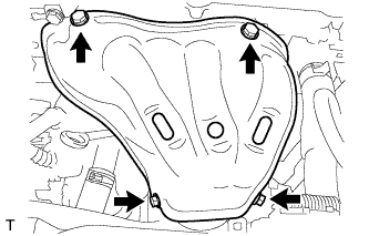 |
Remove the 4 bolts and heat insulator.
| 7. REMOVE EXHAUST MANIFOLD CONVERTER SUB-ASSEMBLY |
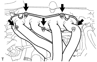 |
Remove the 5 nuts, manifold converter and gasket.
| 8. REMOVE WATER INLET |
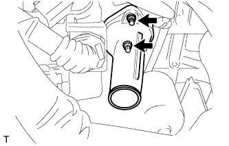 |
Remove the 2 nuts and disconnect the water inlet from the cylinder block.
| 9. REMOVE THERMOSTAT |
| 10. REMOVE NO. 1 WATER BY-PASS PIPE (w/o Oil Cooler) |
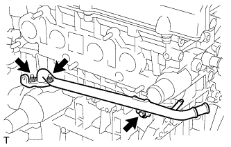 |
Remove the bolt, 2 nuts, pipe and gasket.
| 11. REMOVE OIL COOLER PIPE (w/ ATF Warmer) |
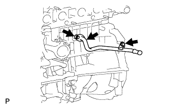 |
Remove the bolt, 2 nuts, pipe and gasket.
| 12. REMOVE UNION BOLT (w/ Oil Cooler) |
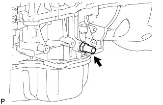 |
Remove the union bolt.
| 13. REMOVE NO. 1 TAPER SCREW PLUG (w/o Oil Cooler) |
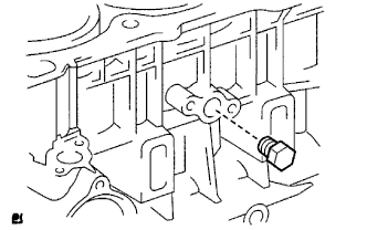 |
Remove the plug from the cylinder block.
| 14. REMOVE NO. 3 WATER BY-PASS PIPE (w/ Oil Cooler) |
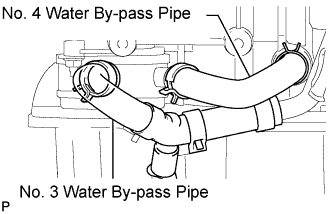 |
Disconnect the No. 3 and No. 4 water by-pass hoses.
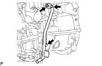 |
Remove the bolt, 2 nuts, pipe and gasket.
| 15. REMOVE OIL FILTER SUB-ASSEMBLY |
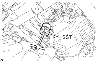 |
Using SST, remove the oil filter.
| 16. REMOVE ENGINE OIL COOLER (w/ Oil Cooler) |
Disconnect the 2 oil cooler hoses from the oil cooler.
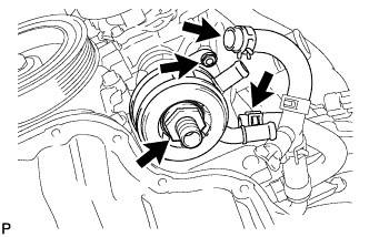 |
Remove the union bolt, nut, plate washer, oil cooler and O-ring.
| 17. REMOVE V-RIBBED BELT TENSIONER ASSEMBLY |
Lift the engine upward using the transmission jack.
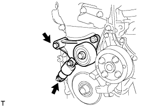 |
Remove the bolt, nut and V-ribbed belt tensioner.
| 18. REMOVE CAMSHAFT TIMING OIL CONTROL VALVE ASSEMBLY |
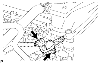 |
Disconnect the oil control valve connector.
Remove the bolt and oil control valve.
| 19. REMOVE KNOCK SENSOR |
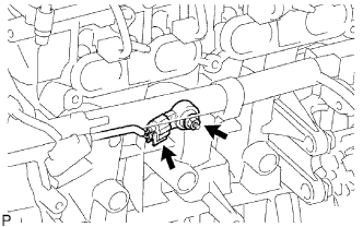 |
Disconnect the sensor connector.
Remove the nut and sensor.
| 20. REMOVE RADIO SETTING CONDENSER |
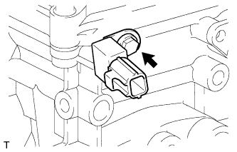 |
Remove the bolt and condenser.
| 21. REMOVE ENGINE OIL PRESSURE SWITCH ASSEMBLY |
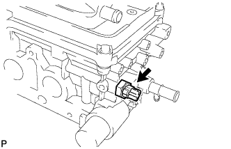 |
Using a 24 mm deep socket wrench, remove the sensor.
| 22. REMOVE ENGINE COOLANT TEMPERATURE SENSOR |
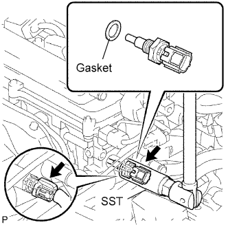 |
Disconnect the sensor connector.
Using SST, remove the sensor and gasket.
| 23. REMOVE CAMSHAFT POSITION SENSOR |
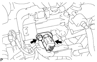 |
Disconnect the sensor connector.
Remove the bolt and sensor.
| 24. REMOVE IGNITION COIL ASSEMBLY |
Disconnect the 4 ignition coil connectors.
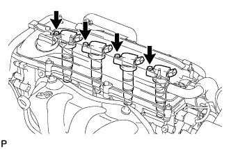 |
Remove the 4 bolts and 4 ignition coils.
| 25. REMOVE SPARK PLUG |
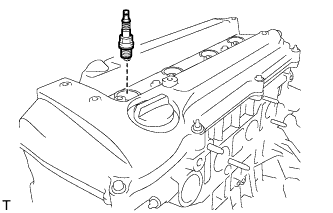 |
| 26. REMOVE OIL FILLER CAP SUB-ASSEMBLY |
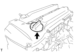 |
| 27. REMOVE OIL FILLER CAP GASKET |
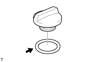 |
| 28. REMOVE VENTILATION VALVE SUB-ASSEMBLY |
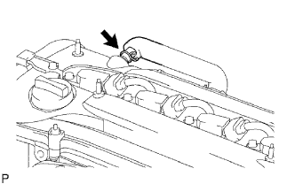 |
Disconnect the ventilation hose from the ventilation valve.
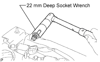 |
Using a 22 mm deep socket wrench, remove the ventilation valve.
| 29. REMOVE CYLINDER HEAD COVER SUB-ASSEMBLY |
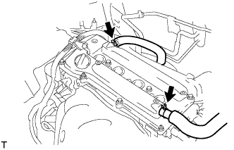 |
Disconnect the 2 ventilation hoses from the cylinder head cover.
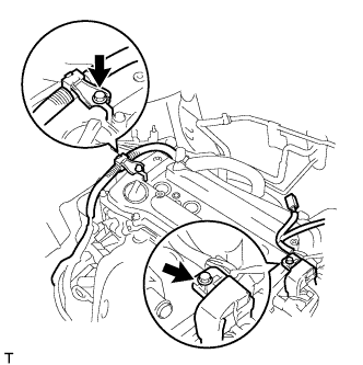 |
Remove the 2 bolts and disconnect the 2 engine wires.
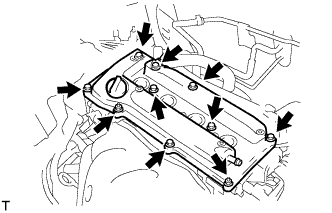 |
Remove the 8 bolts, 2 nuts and cylinder head cover.
| 30. REMOVE CYLINDER HEAD COVER GASKET |
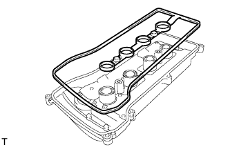 |
| 31. REMOVE OIL FILTER SUB-ASSEMBLY |
|
Using SST, remove the oil filter.
| 32. REMOVE OIL FILTER UNION |
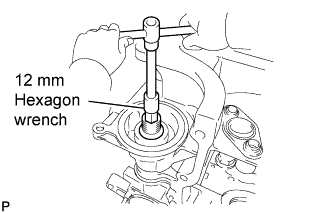 |
Using a 12 mm hexagon wrench, remove the oil filter union.
| 33. REMOVE CRANKSHAFT POSITION SENSOR |
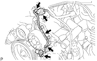 |
Disconnect the sensor connector.
Remove the connector clamp.
Remove the wire harness from the wire harness clamp bracket.
Remove the wire harness clamp.
Remove the bolt and sensor.
| 34. REMOVE WATER PUMP PULLEY |
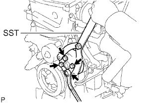 |
Using SST, remove the 4 bolts and water pump pulley.
| 35. REMOVE WATER PUMP ASSEMBLY |
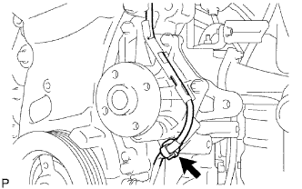 |
Remove the clamp of the crankshaft position sensor from the water pump.
Disconnect the wire of the crankshaft position sensor from the clamp bracket.
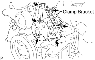 |
Remove the 4 bolts, 2 nuts and clamp bracket.
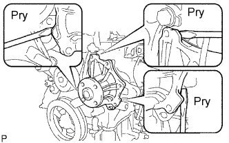 |
Using a screwdriver, pry between the water pump and cylinder block, and then remove the water pump.
| 36. REMOVE OIL PAN DRAIN PLUG |
Remove the oil pan drain plug and gasket.
| 37. REMOVE OIL PAN SUB-ASSEMBLY |
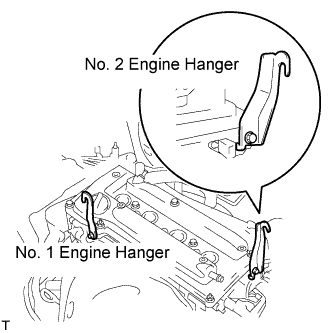 |
Install the No. 1 and No. 2 engine hangers with the bolts.
| Item | Part No. |
| No. 1 engine hanger | 12281-28010 |
| No. 2 engine hanger | 12282-28010 |
| Bolt | 91512-61020 |
Attach the sling device to the engine hangers and chain block.
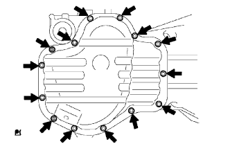 |
Remove the 12 bolts and 2 nuts.
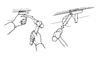 |
Insert the blade of an oil pan seal cutter between the crankcase, chain cover and oil pan and cut off the applied sealer and remove the oil pan.
| 38. REMOVE CRANKSHAFT PULLEY |
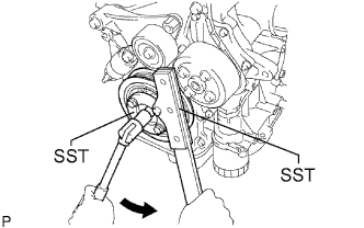 |
Using SST, fix the pulley in place and loosen the pulley bolt.
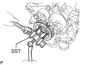 |
Remove the crankshaft pulley.
| 39. REMOVE NO. 1 CHAIN TENSIONER ASSEMBLY |
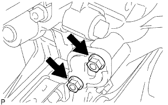 |
Remove the 2 nuts, chain tensioner and gasket.
| 40. REMOVE TIMING CHAIN COVER SUB-ASSEMBLY |
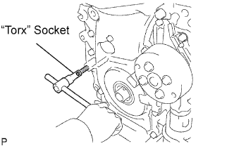 |
Using an E10 "torx" socket, remove the stud bolt for the V-ribbed belt tensioner.
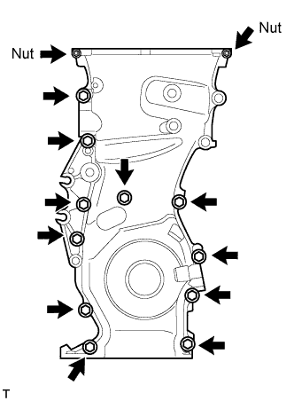 |
Remove the 11 bolts and 2 nuts.
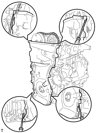 |
Remove the timing chain cover by prying the portions between the timing chain cover, cylinder head and cylinder block with a screwdriver.
| 41. REMOVE TIMING CHAIN COVER OIL SEAL |
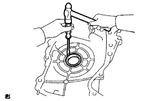 |
Using a screwdriver and hammer, tap out the oil seal.
Place the oil seal retainer on wooden blocks.
Apply multi-purpose grease to the lip of a new oil seal.
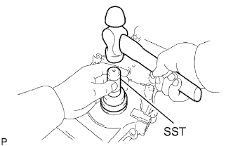 |
Using SST and a hammer, tap in a new oil seal until its surface is flush with the timing gear case edge.
| 42. REMOVE NO. 1 CRANKSHAFT POSITION SENSOR PLATE |
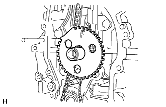 |
| 43. REMOVE TIMING CHAIN GUIDE |
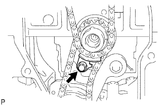 |
Remove the bolt and timing chain guide.
| 44. REMOVE CHAIN TENSIONER SLIPPER |
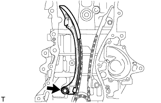 |
Remove the bolt and chain tensioner slipper.
| 45. REMOVE CHAIN SUB-ASSEMBLY |
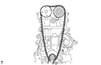 |
| 46. REMOVE NO. 1 CHAIN VIBRATION DAMPER |
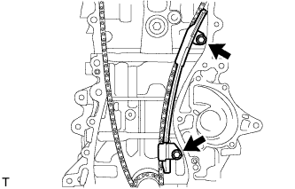 |
Remove the 2 bolts and chain vibration damper.
| 47. REMOVE CRANKSHAFT TIMING SPROCKET |
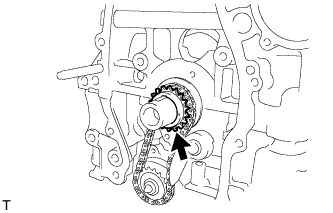 |
| 48. REMOVE NO. 2 CHAIN SUB-ASSEMBLY |
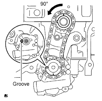 |
Turn the crankshaft by 90° counterclockwise to align the adjusting hole of the oil pump drive shaft sprocket with the groove of the oil pump.
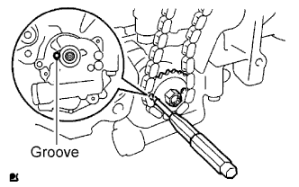 |
Insert a 4 mm diameter bar into the adjusting hole of the oil pump drive shaft sprocket to lock the gear in position, and then remove the nut.
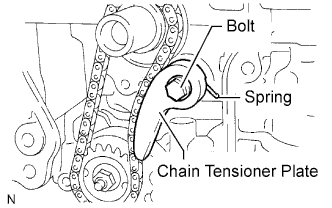 |
Remove the bolt, chain tensioner plate and spring.
Remove the oil pump drive sprocket, oil pump drive shaft sprocket and No. 2 chain.
| 49. REMOVE OIL PUMP DRIVE GEAR |
| 50. REMOVE OIL PUMP ASSEMBLY |
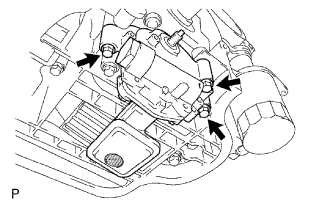 |
Remove the 3 bolts, oil pump and gasket.
| 51. REMOVE CAMSHAFT |
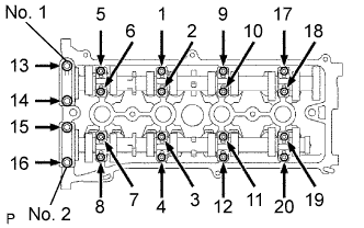 |
Using several steps, uniformly loosen and remove the 20 bearing cap bolts in the sequence shown in the illustration.
Remove the 10 bearing caps, then remove the camshaft and No. 2 camshaft.
| 52. REMOVE CYLINDER HEAD SUB-ASSEMBLY |
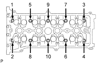 |
Using several steps, uniformly loosen and remove the 10 cylinder head bolts and 10 plate washers with a 10 mm bi-hexagon wrench in the sequence shown in the illustration.
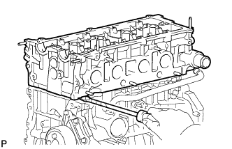 |
Using a screwdriver with its tip wrapped with tape, pry between the cylinder head and cylinder block, and remove the cylinder head.
| 53. REMOVE CYLINDER HEAD GASKET |
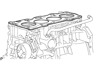 |
| 54. REMOVE CYLINDER BLOCK WATER DRAIN COCK SUB-ASSEMBLY |
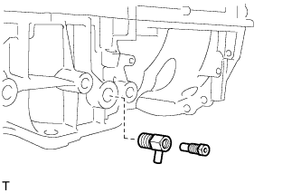 |
| 55. REMOVE OIL CONTROL VALVE FILTER |
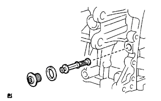 |
Using a 6 mm socket hexagon wrench, remove the plug and gasket.
Remove the oil control valve filter.
| 56. REMOVE ENGINE REAR OIL SEAL |
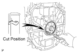 |
Using a knife, cut off the lip of the oil seal.
Using a screwdriver with its tip wrapped with tape, pry out the oil seal.
| 57. REMOVE STIFFENING CRANKCASE ASSEMBLY |
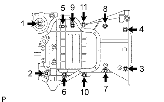 |
Using several steps, uniformly loosen and remove the 11 bolts in the sequence shown in the illustration.
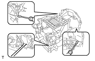 |
Remove the crankcase by prying the portions between the crankcase and cylinder block.
Remove the O-ring from the cylinder block.
| 58. INSPECT CONNECTING ROD THRUST CLEARANCE |
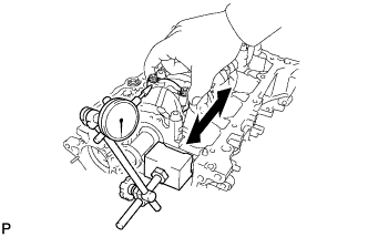 |
Using a dial indicator, measure the thrust clearance while moving the connecting rod back and forth.
| 59. INSPECT CONNECTING ROD OIL CLEARANCE |
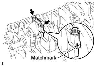 |
Using marking paint, write the matched cylinder number on each connecting rod and cap.
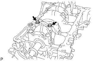 |
Using a 12 mm socket wrench, remove the 2 bolts and connecting rod cap.
Clean the crank pin and bearing.
Check the crank pin and bearing for pitting and scratches.
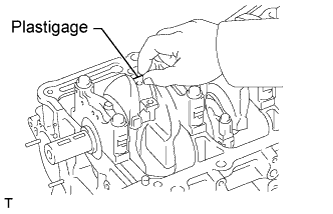 |
Lay a strip of Plastigage on the crank pin.
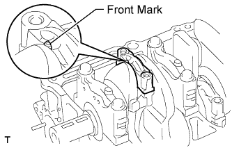 |
Check that the front mark of the connecting rod cap is facing in the correct direction.
Apply a light coat of engine oil to the threads and under the heads of the connecting rod bolts.
Using a 12 mm socket wrench, tighten the bolts in several passes to the specified torque.
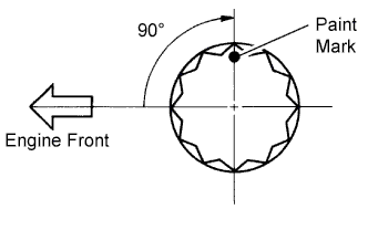 |
Mark the front of the connecting rod bolts with paint.
Retighten the cap bolts 90° as shown in the illustration.
Check that the crankshaft turns smoothly.
Using a 12 mm socket wrench, remove the 2 bolts and connecting rod cap.
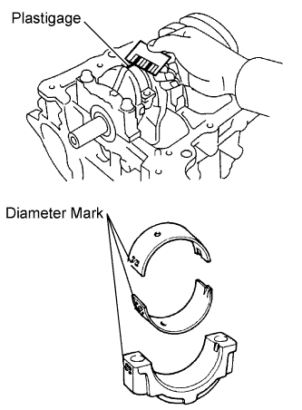 |
Measure the Plastigage at its widest point.
| Mark | Specified Condition |
| Mark 1 | 51.000 to 51.007 mm (2.0079 to 2.0082 in.) |
| Mark 2 | 51.008 to 51.013 mm (2.0082 to 2.0084 in.) |
| Mark 3 | 51.014 to 51.020 mm (2.0084 to 2.0087 in.) |
| Mark | Specified Condition |
| Mark 1 | 1.485 to 1.488 mm (0.0585 to 0.0586 in.) |
| Mark 2 | 1.489 to 1.491 mm (0.0586 to 0.0587 in.) |
| Mark 3 | 1.492 to 1.494 mm (0.0587 to 0.0588 in.) |
| Mark | Specified Condition |
| - | 47.990 to 48.000 (1.8894 to 1.8898 in.) |
| 60. REMOVE PISTON WITH CONNECTING ROD |
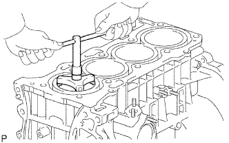 |
Using a ridge reamer, remove all the carbon from the top of the cylinder.
Push the piston, connecting rod assembly and upper bearing through the top of the cylinder block.
| 61. REMOVE CONNECTING ROD BEARING |
| 62. REMOVE PISTON RING SET |
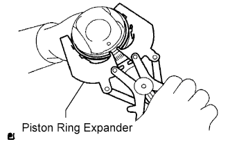 |
Using a piston ring expander, remove the 2 compression rings.
Remove the 2 side rails and expander by hand.
| 63. REMOVE PISTON PIN HOLE SNAP RING |
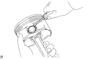 |
Using a small screwdriver, pry out the 2 snap rings.
| 64. REMOVE PISTON |
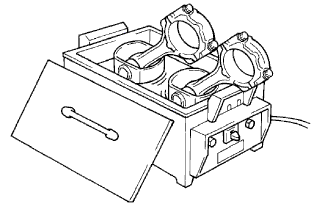 |
Gradually heat the piston up to 80 to 90°C (176 to 194°F).
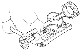 |
Using a plastic-faced hammer and brass bar, lightly tap out the piston pin, then remove the connecting rod.
| 65. INSPECT CRANKSHAFT THRUST CLEARANCE |
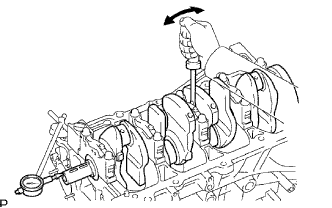 |
Using a dial indicator, measure the thrust clearance while prying the crankshaft back and forth with a screwdriver.
| 66. INSPECT CRANKSHAFT OIL CLEARANCE |
Clean each main journal and bearing.
Check each main journal and bearing for pitting and scratches.
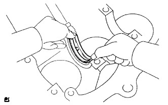 |
Install the upper bearing with an oil groove onto the cylinder block.
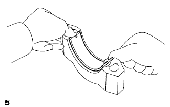 |
Install the lower bearing onto the bearing cap.
Place the crankshaft onto the cylinder block.
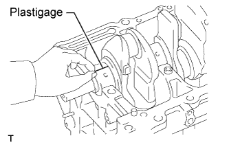 |
Lay a strip of Plastigage across each journal.
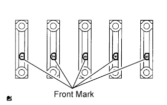 |
Examine the front marks and numbers, and install the bearing caps onto the cylinder block in the order shown in the illustration.
Apply a light coat of engine oil to the threads and under the heads of the bearing cap bolts.
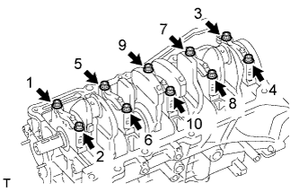 |
Using several steps, uniformly install and tighten the 10 bearing cap bolts in the sequence shown in the illustration.
|
Mark the front of the bearing cap bolts with paint.
Retighten the 10 bearing cap bolts by 90°.
Check that the paint marks are at a 90° angle to the front.
Remove the bearing caps.
Measure the Plastigage at its widest point.
| Cylinder block + Crankshaft | 0 to 2 | 3 to 5 | 6 to 8 | 9 to 11 |
| Use bearing | "1" | "2" | "3" | "4" |
| Mark | Specified Condition |
| 0 | 59.000 to 59.002 mm (2.3228 to 2.3229 in.) |
| 1 | 59.003 to 59.004 mm (2.3230 to 2.3230 in.) |
| 2 | 59.005 to 59.006 mm (2.3230 to 2.3231 in.) |
| 3 | 59.007 to 59.009 mm (2.3231 to 2.3232 in.) |
| 4 | 59.010 to 59.011 mm (2.3232 to 2.3233 in.) |
| 5 | 59.012 to 59.013 mm (2.3233 to 2.3234 in.) |
| 6 | 59.014 to 59.016 mm (2.3234 to 2.3235 in.) |
| Mark | Specified Condition |
| 0 | 54.999 to 55.000 mm (2.1653 to 2.1654 in.) |
| 1 | 54.997 to 54.998 mm (2.1652 to 2.1653 in.) |
| 2 | 54.995 to 54.996 mm (2.1652 to 2.1652 in.) |
| 3 | 54.993 to 54.994 mm (2.1651 to 2.1651 in.) |
| 4 | 54.991 to 54.992 mm (2.1650 to 2.1650 in.) |
| 5 | 54.988 to 54.990 mm (2.1649 to 2.1650 in.) |
| Mark | Specified Condition |
| 1 | 1.993 to 1.996 mm (0.0785 to 0.0786 in.) |
| 2 | 1.997 to 1.999 mm (0.0786 to 0.0787 in.) |
| 3 | 2.000 to 2.002 mm (0.0787 to 0.0788 in.) |
| 4 | 2.003 to 2.005 mm (0.0789 to 0.0789 in.) |
| 67. REMOVE CRANKSHAFT |
|
Using several steps, uniformly loosen and remove the 10 bearing cap bolts in the sequence shown in the illustration.
Remove the 5 bearing caps from the cylinder block.
Remove the crankshaft from the cylinder block.
| 68. REMOVE CRANKSHAFT THRUST WASHER UPPER |
| 69. REMOVE CRANKSHAFT BEARING |
| 70. REMOVE NO. 2 CRANKSHAFT BEARING |