 |
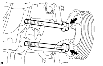
Loosen the 2 bolts and remove the idler bracket with the 2 bolts.
ENGINE UNIT > DISASSEMBLY |
| 1. REMOVE IDLER PULLEY |
|
Loosen the 2 bolts and remove the idler bracket with the 2 bolts.
| 2. REMOVE OIL DIPSTICK |
| 3. REMOVE OIL DIPSTICK GUIDE |
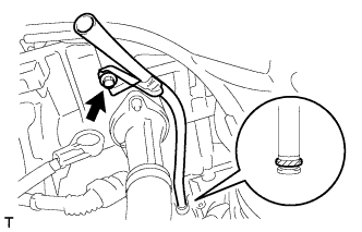 |
Remove the bolt and guide.
Remove the O-ring from the guide.
| 4. REMOVE MANIFOLD STAY |
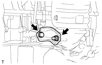 |
Remove the bolt, nut and stay.
| 5. REMOVE NO. 2 MANIFOLD STAY |
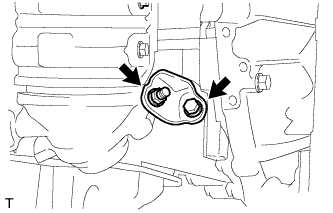 |
Remove the bolt, nut and stay.
| 6. REMOVE NO. 1 EXHAUST MANIFOLD HEAT INSULATOR |
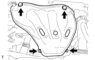 |
Remove the 4 bolts and heat insulator.
| 7. REMOVE EXHAUST MANIFOLD CONVERTER SUB-ASSEMBLY |
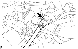 |
Disconnect the air-fuel ratio sensor connector.
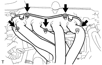 |
Remove the 5 nuts, manifold converter and gasket.
| 8. REMOVE WATER INLET |
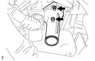 |
Remove the 2 nuts and disconnect the water inlet from the cylinder block.
| 9. REMOVE THERMOSTAT |
| 10. REMOVE NO. 1 WATER BY-PASS PIPE |
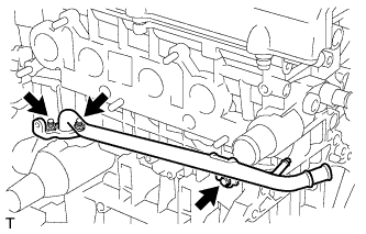 |
Remove the bolt, 2 nuts, pipe and gasket.
| 11. REMOVE OIL COOLER PIPE (w/ Oil Cooler) |
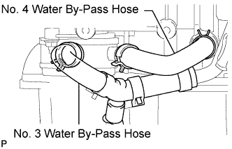 |
Disconnect the No. 3 and No. 4 water by-pass hose.
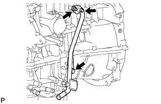 |
Remove the bolt, 2 nuts, pipe and gasket.
| 12. REMOVE UNION BOLT (w/ Oil Cooler) |
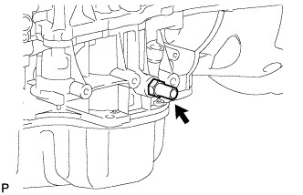 |
Remove the union bolt.
| 13. REMOVE NO. 1 TAPER SCREW PLUG (w/o Oil Cooler) |
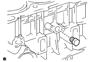 |
Remove the plug from the cylinder block.
| 14. REMOVE ENGINE OIL COOLER (w/ Oil Cooler) |
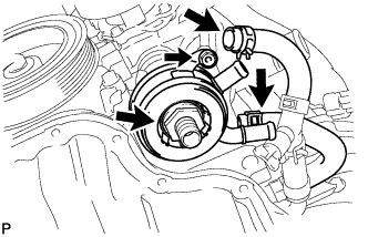 |
Disconnect the 2 oil cooler hoses from the oil cooler.
Remove the union bolt, plate washer, nut, oil cooler and O-ring.
| 15. REMOVE V-RIBBED BELT TENSIONER ASSEMBLY |
Lift the engine upward using the transmission jack.
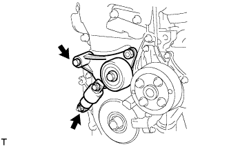 |
Remove the bolt, nut and V-ribbed belt tensioner.
| 16. REMOVE CAMSHAFT TIMING OIL CONTROL VALVE ASSEMBLY |
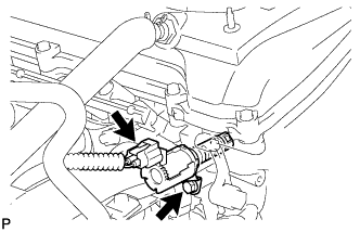 |
Disconnect the oil control valve connector.
Remove the bolt and oil control valve.
| 17. REMOVE KNOCK SENSOR |
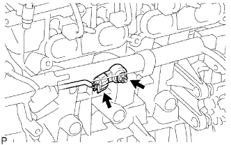 |
Disconnect the sensor connector.
Remove the nut and sensor.
| 18. REMOVE RADIO SETTING CONDENSER |
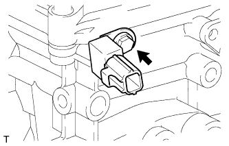 |
Remove the bolt and condenser.
| 19. REMOVE OIL PRESSURE SWITCH ASSEMBLY |
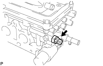 |
Using a 24 mm deep socket wrench, remove the sensor.
| 20. REMOVE ENGINE COOLANT TEMPERATURE SENSOR |
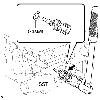 |
Using SST, remove the sensor and gasket.
| 21. REMOVE CAMSHAFT POSITION SENSOR |
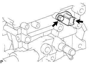 |
Remove the bolt and sensor.
| 22. REMOVE IGNITION COIL ASSEMBLY |
Disconnect the 4 ignition coil connectors.
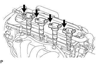 |
Remove the 4 bolts and 4 ignition coils.
| 23. REMOVE SPARK PLUG |
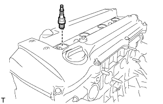 |
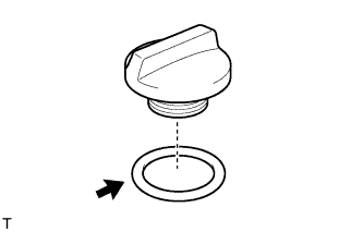
| 24. REMOVE OIL FILLER CAP SUB-ASSEMBLY |
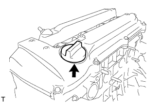 |
| 25. REMOVE OIL FILLER CAP GASKET |
 |
| 26. REMOVE VENTILATION VALVE SUB-ASSEMBLY |
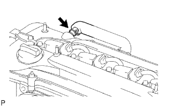 |
Disconnect the ventilation hose from the ventilation valve.
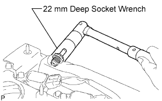 |
Using a 22 mm deep socket wrench, remove the ventilation valve.
| 27. REMOVE CAMSHAFT TIMING OIL CONTROL VALVE ASSEMBLY |
Remove the bolt and control valve.
| 28. REMOVE CYLINDER HEAD COVER SUB-ASSEMBLY |
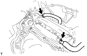 |
Disconnect the 2 ventilation hoses from the cylinder head cover.
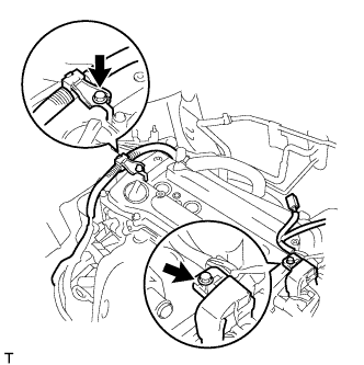 |
Remove the 2 bolts and disconnect the 2 engine wires.
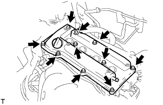 |
Remove the 8 bolts, 2 nuts and cylinder head cover.
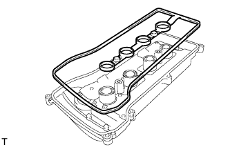
| 29. REMOVE CYLINDER HEAD COVER GASKET |
 |
| 30. REMOVE OIL FILTER SUB-ASSEMBLY |
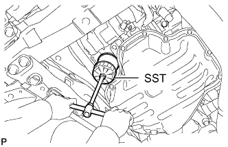 |
Using SST, remove the oil filter.
| 31. REMOVE OIL FILTER UNION |
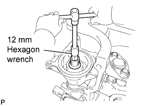 |
Using a 12 mm hexagon wrench, remove the oil filter union.
| 32. REMOVE CRANKSHAFT POSITION SENSOR |
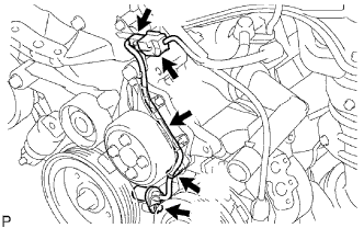 |
Disconnect the sensor connector.
Remove the connector clamp.
Remove the wire harness from the wire harness clamp bracket.
Remove the wire harness clamp.
Remove the bolt and sensor.
| 33. REMOVE WATER PUMP PULLEY |
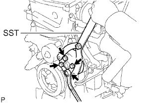 |
Using SST, remove the 4 bolts and water pump pulley.
| 34. REMOVE WATER PUMP ASSEMBLY |
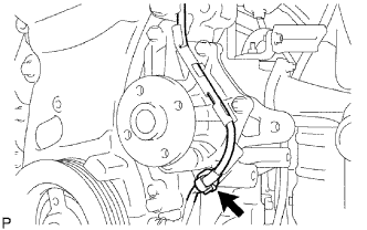 |
Remove the clamp of the crankshaft position sensor from the water pump.
Disconnect the wire of the crankshaft position sensor from the clamp bracket.
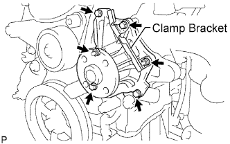 |
Remove the 4 bolts, 2 nuts and clamp bracket.
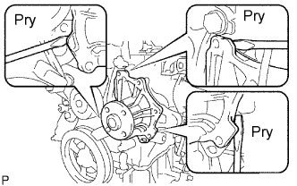 |
Using a screwdriver, pry between the water pump and cylinder block, and then remove the water pump.
| 35. REMOVE OIL PAN DRAIN PLUG |
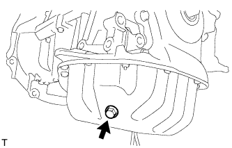 |
Remove the oil pan drain plug and gasket.
| 36. REMOVE OIL PAN SUB-ASSEMBLY |
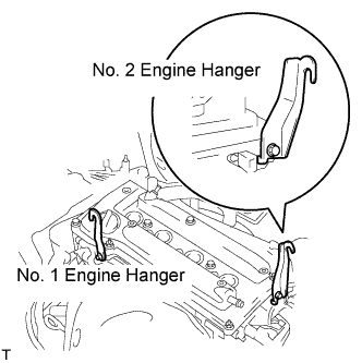 |
Install the No. 1 and No. 2 engine hangers with the bolts.
| Item | Part No. |
| No. 1 engine hanger | 12281-28010 |
| No. 2 engine hanger | 12282-28010 |
| Bolt | 91512-61020 |
Attach the sling device to the engine hangers and chain block.
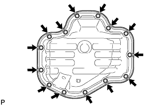 |
Remove the 12 bolts and 2 nuts.
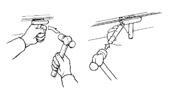 |
Insert the blade of an oil pan seal cutter between the crankcase, chain cover and oil pan and cut off the applied sealer and remove the oil pan.
| 37. REMOVE CRANKSHAFT PULLEY |
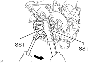 |
Using SST, fix the pulley in place and loosen the pulley bolt.
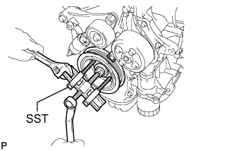 |
Remove the crankshaft pulley.
| 38. REMOVE NO. 1 CHAIN TENSIONER ASSEMBLY |
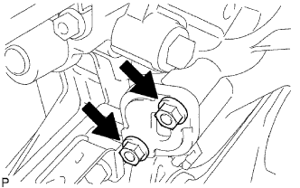 |
Remove the 2 nuts, chain tensioner and gasket.
| 39. REMOVE TIMING CHAIN COVER SUB-ASSEMBLY |
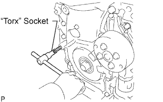 |
Using an E10 "torx" socket, remove the stud bolt for the V-ribbed belt tensioner.
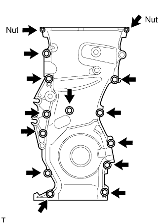 |
Remove the 12 bolts and 2 nuts.
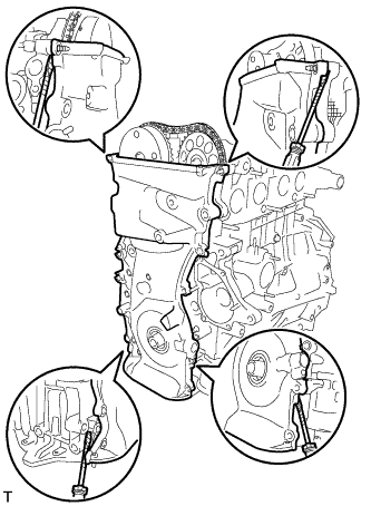 |
Remove the timing chain cover by prying the portions between the timing chain cover, cylinder head and cylinder block with a screwdriver.
| 40. REMOVE NO. 1 CRANKSHAFT POSITION SENSOR PLATE |
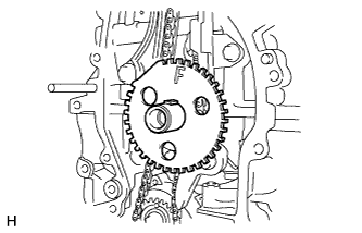 |
| 41. REMOVE TIMING CHAIN GUIDE |
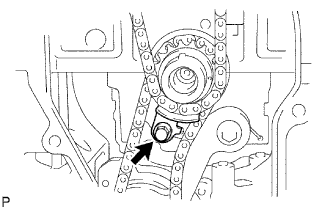 |
Remove the bolt and timing chain guide.
| 42. REMOVE CHAIN TENSIONER SLIPPER |
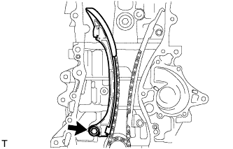 |
Remove the bolt and chain tensioner slipper.
| 43. REMOVE CHAIN SUB-ASSEMBLY |
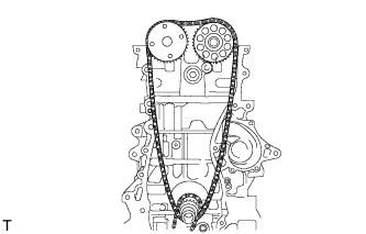 |
| 44. REMOVE NO. 1 CHAIN VIBRATION DAMPER |
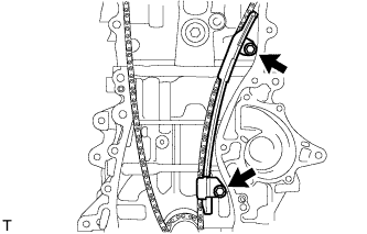 |
Remove the 2 bolts and chain vibration damper.
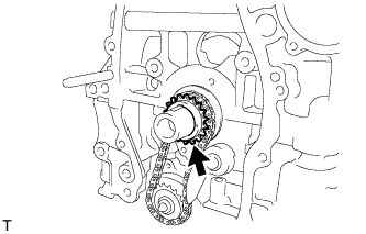
| 45. REMOVE CRANKSHAFT TIMING SPROCKET |
 |
| 46. REMOVE NO. 2 CHAIN SUB-ASSEMBLY |
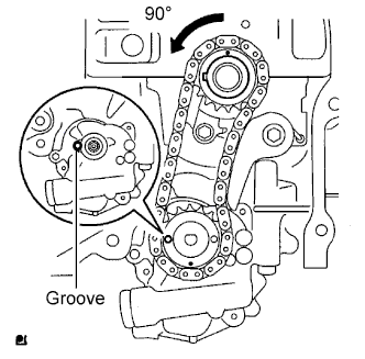 |
Turn the crankshaft by 90°counterclockwise to align the adjusting hole of the oil pump drive shaft sprocket with the groove of the oil pump.
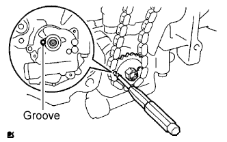 |
Insert a 4 mm diameter bar into the adjusting hole of the oil pump drive shaft sprocket to lock the gear in position, and then remove the nut.
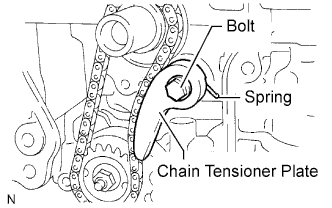 |
Remove the bolt, chain tensioner plate and spring.
Remove the oil pump drive sprocket, oil pump drive shaft sprocket and No. 2 chain.
| 47. REMOVE OIL PUMP DRIVE GEAR |
| 48. REMOVE OIL PUMP ASSEMBLY |
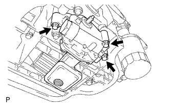 |
Remove the 3 bolts, oil pump and gasket.
| 49. REMOVE CAMSHAFT |
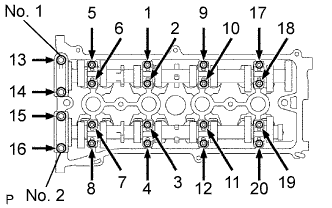 |
Using several steps, uniformly loosen and remove the 20 bearing cap bolts in the sequence shown in the illustration.
Remove the 10 bearing caps, then remove the camshaft and No. 2 camshaft.
| 50. REMOVE CYLINDER HEAD SUB-ASSEMBLY |
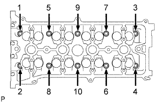 |
Using several steps, uniformly loosen and remove the 10 cylinder head bolts and 10 plate washers with a 10 mm bi-hexagon wrench in the sequence shown in the illustration.
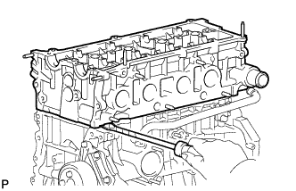 |
Using a screwdriver, pry between the cylinder head and cylinder block, and remove the cylinder head.
| 51. REMOVE CYLINDER HEAD GASKET |
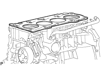 |
| 52. REMOVE CYLINDER BLOCK WATER JACKET SPACER |
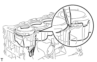 |
Using needle-nose pliers, remove the cylinder block water jacket spacer from the water jacket.
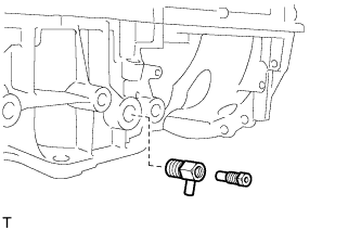
| 53. REMOVE CYLINDER BLOCK WATER DRAIN COCK SUB-ASSEMBLY |
 |
| 54. REMOVE OIL CONTROL VALVE FILTER |
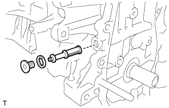 |
Using a 6 mm socket hexagon wrench, remove the plug and gasket.
Remove the oil control valve filter.
| 55. INSPECT BALANCE SHAFT THRUST CLEARANCE |
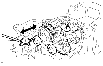 |
Using a dial indicator, measure the thrust clearance while moving the balance shaft back and forth.
| 56. INSPECT BALANCE SHAFT OIL CLEARANCE |
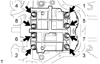 |
Using several steps, uniformly loosen and remove the 8 bolts in the sequence shown in the illustration.
Remove the balance shaft housing from the crankcase.
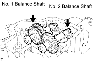 |
Lift out the No. 1 and No. 2 balance shafts.
Clean each bearing and journal.
Check each bearing and journal for pitting and scratches.
If a bearing or journal is damaged, replace the bearings. If necessary, replace the balance shaft.
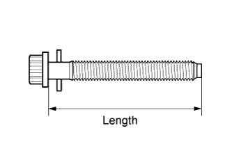 |
Inspect the balance shaft bolt.
Using a vernier caliper, measure the length of the bolts from the seat to the end.
Place the No. 1 and No. 2 balance shafts onto the crankcase.
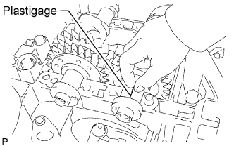 |
Lay a strip of Plastigage across each journal.
Install the balance shaft housing.
Apply a light coat of engine oil on the threads and under the heads of the bolts.
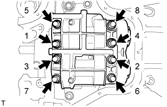 |
Using several steps, uniformly install and tighten the 8 bolts in the sequence shown in the illustration.
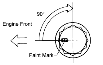 |
Mark the front of the bolts with paint.
Retighten the bolts 90° as shown in the illustration.
Check that the paint mark is now at a 90° angle to the front.
Remove the balance shaft housing from the crankcase.
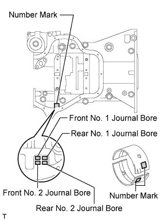 |
Measure the Plastigage at its widest point.
| Item | Specified Condition |
| Mark 1 | 26.000 to 26.006 mm (1.0236 to 1.0239 in.) |
| Mark 2 | 26.007 to 26.012 mm (1.0239 to 1.0214 in.) |
| Mark 3 | 26.013 to 26.018 mm (1.0241 to 1.0243 in.) |
| Item | Specified Condition |
| Mark 1 | 1.486 to 1.489 mm (0.05850 to 0.05862 in.) |
| Mark 2 | 1.490 to 1.492 mm (0.05866 to 0.05874 in.) |
| Mark 3 | 1.493 to 1.495 mm (0.0585 to 0.0586 in.) |
| 57. REMOVE BALANCE SHAFT |
|
| 58. REMOVE NO. 1 BALANCE SHAFT BEARING |
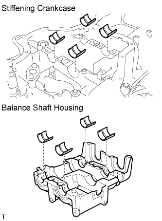 |
| 59. REMOVE ENGINE REAR OIL SEAL |
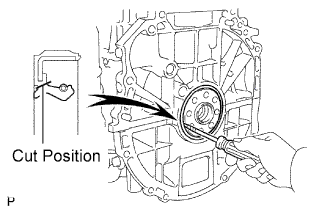 |
Using a knife, cut off the lip of the oil seal.
Using a screwdriver with its tip wrapped with tape, pry out the oil seal.
| 60. REMOVE STIFFENING CRANKCASE ASSEMBLY |
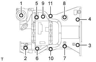 |
Using several steps, uniformly loosen and remove the 11 bolts in the sequence shown in the illustration.
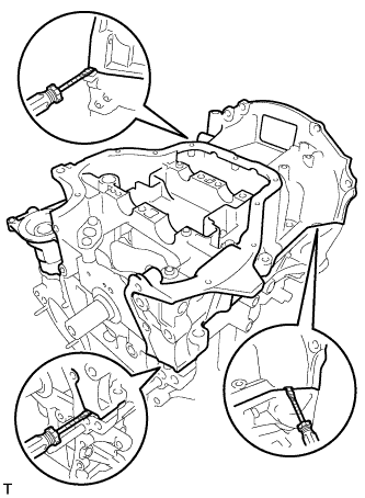 |
Remove the crankcase by prying the portions between the crankcase and cylinder block.
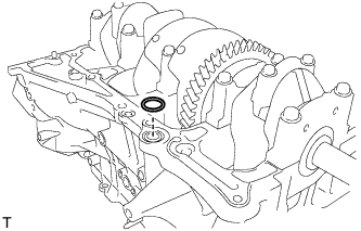 |
Remove the O-ring from the cylinder block.
| 61. INSPECT CONNECTING ROD THRUST CLEARANCE |
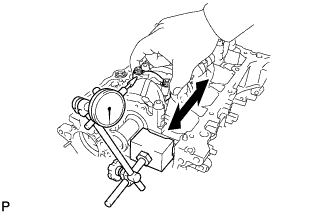 |
Using a dial indicator, measure the thrust clearance while moving the connecting rod back and forth.
| 62. INSPECT CONNECTING ROD OIL CLEARANCE |
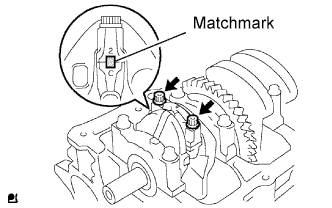 |
Using marking paint, write the matched cylinder number on each connecting rod and cap.
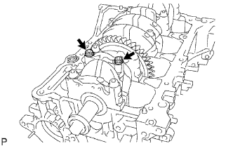 |
Using a 12 mm socket wrench, remove the 2 bolts and connecting rod cap.
Clean the crank pin and bearing.
Check the crank pin and bearing for pitting and scratches.
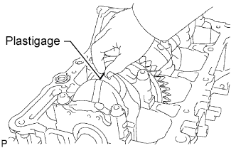 |
Lay a strip of Plastigage on the crank pin.
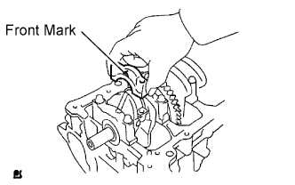 |
Check that the front mark of the connecting rod cap is facing in the correct direction.
Apply a light coat of engine oil to the threads and under the heads of the connecting rod bolts.
Using a 12 mm socket wrench, tighten the bolts in several passes to the specified torque.
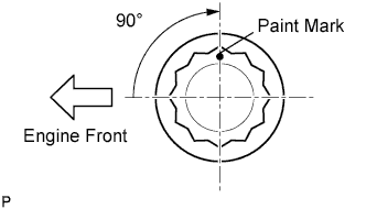 |
Mark the front of the connecting rod bolts with paint.
Retighten the cap bolts 90° as shown in the illustration.
Check that the crankshaft turns smoothly.
Using a 12 mm socket wrench, remove the 2 bolts and connecting rod cap.
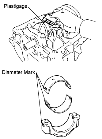 |
Measure the Plastigage at its widest point.
| Mark | Specified Condition |
| Mark 1 | 51.000 to 51.007 mm (2.0079 to 2.0082 in.) |
| Mark 2 | 51.008 to 51.013 mm (2.0082 to 2.0084 in.) |
| Mark 3 | 51.014 to 51.020 mm (2.0084 to 2.0087 in.) |
| Mark | Specified Condition |
| Mark 1 | 1.485 to 1.488 mm (0.0585 to 0.0586 in.) |
| Mark 2 | 1.489 to 1.491 mm (0.0586 to 0.0587 in.) |
| Mark 3 | 1.492 to 1.494 mm (0.0587 to 0.0588 in.) |
| 63. REMOVE PISTON WITH CONNECTING ROD |
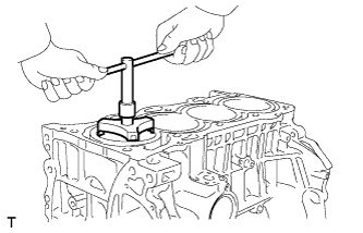 |
Using a ridge reamer, remove all the carbon from the top of the cylinder.
Push the piston, connecting rod assembly and upper bearing through the top of the cylinder block.
| 64. REMOVE CONNECTING ROD BEARING |
| 65. REMOVE PISTON RING SET |
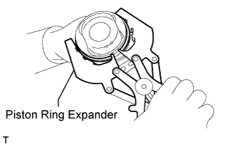 |
Using a piston ring expander, remove the 2 compression rings.
Remove the oil ring and expander by hand.
| 66. REMOVE PISTON PIN HOLE SNAP RING |
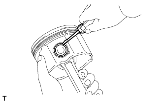 |
Using a small screwdriver, pry out the 2 snap rings.
| 67. REMOVE PISTON |
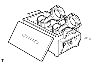 |
Gradually heat the piston up to 80 to 90°C (176 to 194°F).
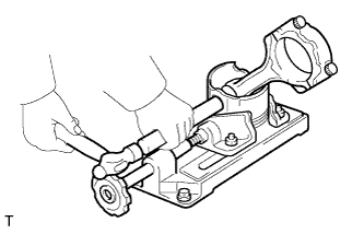 |
Using a plastic hammer and brass bar, lightly tap out the piston pin, then remove the connecting rod.
| 68. INSPECT CRANKSHAFT THRUST CLEARANCE |
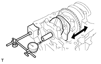 |
Using a dial indicator, measure the thrust clearance while prying the crankshaft back and forth with a screwdriver.
| 69. INSPECT CRANKSHAFT OIL CLEARANCE |
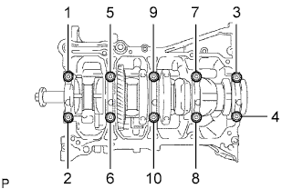 |
Using several steps, uniformly loosen and remove the 10 bearing cap bolts in the sequence shown in the illustration.
Remove the 5 bearing caps from the cylinder block.
Remove the crankshaft.
Clean each main journal and bearing.
Check each main journal and bearing for pitting and scratches.
Place the crankshaft onto the cylinder block.
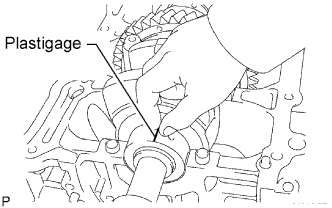 |
Lay a strip of Plastigage across each journal.
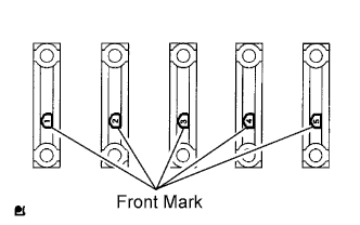 |
Examine the front marks and numbers, and install the bearing caps onto the cylinder block in the order shown in the illustration.
Apply a light coat of engine oil to the threads and under the heads of the crankshaft bearing cap set bolts.
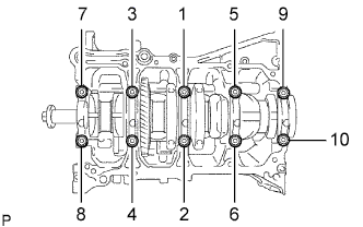 |
Using several steps, uniformly install and tighten the 10 bearing cap bolts in the sequence shown in the illustration.
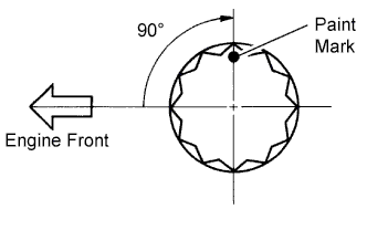 |
Mark the front of the bearing cap bolts with paint.
Retighten the 10 bearing cap bolts by 90°.
Check that the paint marks are at a 90° angle to the front.
|
Remove the crankshaft bearing caps.
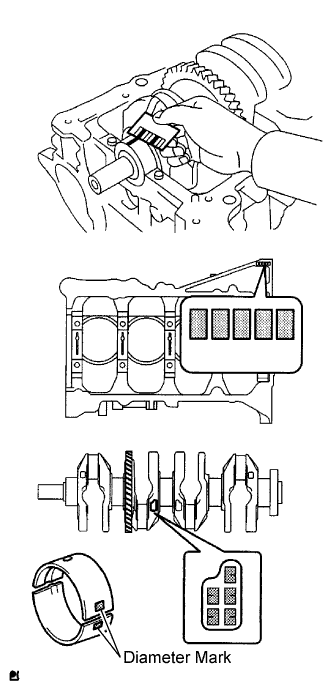 |
Measure the Plastigage at its widest point.
| Cylinder block + Crankshaft | 0 to 2 | 3 to 5 | 6 to 8 | 9 to 11 |
| Use bearing | "1" | "2" | "3" | "4" |
| Mark | Specified Condition |
| 0 | 59.000 to 59.002 mm (2.3228 to 2.3229 in.) |
| 1 | 59.003 to 59.004 mm (2.3230 to 2.3230 in.) |
| 2 | 59.005 to 59.006 mm (2.3230 to 2.3231 in.) |
| 3 | 59.007 to 59.009 mm (2.3231 to 2.3232 in.) |
| 4 | 59.010 to 59.011 mm (2.3232 to 2.3233 in.) |
| 5 | 59.012 to 59.013 mm (2.3233 to 2.3234 in.) |
| 6 | 59.014 to 59.016 mm (2.3234 to 2.3235 in.) |
| Mark | Specified Condition |
| 0 | 54.999 to 55.000 mm (2.1653 to 2.1654 in.) |
| 1 | 54.997 to 54.998 mm (2.1652 to 2.1653 in.) |
| 2 | 54.995 to 54.996 mm (2.1652 to 2.1652 in.) |
| 3 | 54.993 to 54.994 mm (2.1651 to 2.1651 in.) |
| 4 | 54.991 to 54.992 mm (2.1650 to 2.1650 in.) |
| 5 | 54.988 to 54.990 mm (2.1649 to 2.1650 in.) |
| Mark | Specified Condition |
| 1 | 1.993 to 1.996 mm (0.0785 to 0.0786 in.) |
| 2 | 1.997 to 1.999 mm (0.0786 to 0.0787 in.) |
| 3 | 2.000 to 2.002 mm (0.0787 to 0.0788 in.) |
| 4 | 2.003 to 2.005 mm (0.0789 to 0.0789 in.) |
| 70. REMOVE CRANKSHAFT |
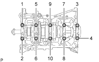 |
Using several steps, uniformly loosen and remove the 10 bearing cap bolts in the sequence shown in the illustration.
Remove the 5 bearing caps from the cylinder block.
Remove the crankshaft from the cylinder block.
| 71. REMOVE CRANKSHAFT THRUST WASHER UPPER |
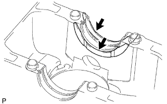 |
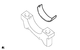
| 72. REMOVE CRANKSHAFT BEARING |
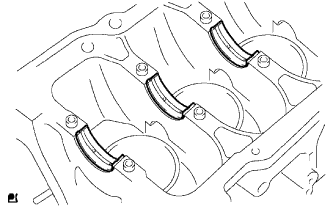 |
| 73. REMOVE NO. 2 CRANKSHAFT BEARING |
 |
| 74. REMOVE NO. 1 OIL NOZZLE SUB-ASSEMBLY |
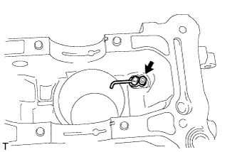 |
Remove the 4 bolts and 4 oil nozzle.
| 75. INSPECT NO. 1 OIL NOZZLE SUB-ASSEMBLY |
Check the oil nozzle for damage or clogging.
If necessary, replace the No. 1 oil nozzle sub-assembly.