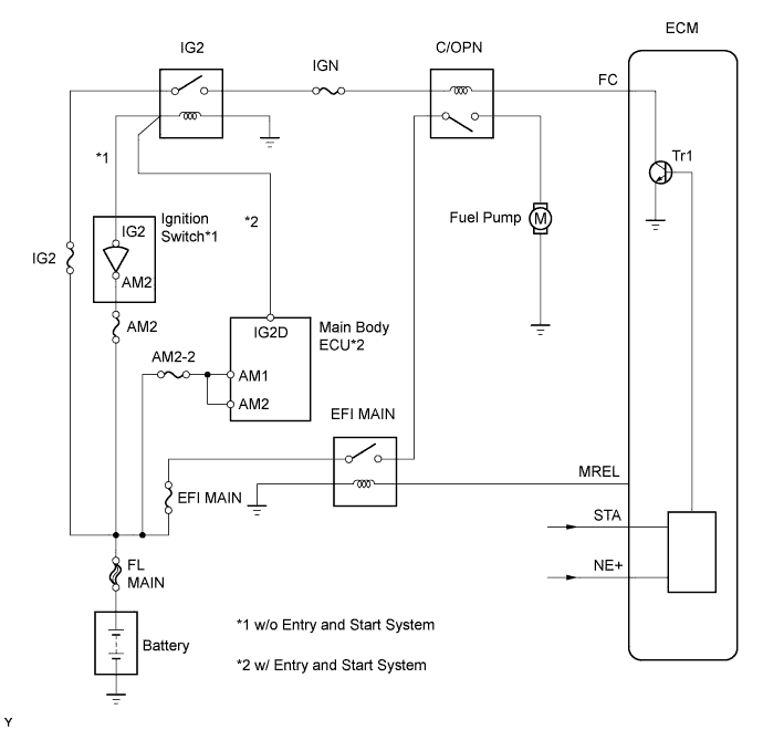
SFI SYSTEM > Fuel Pump Control Circuit |
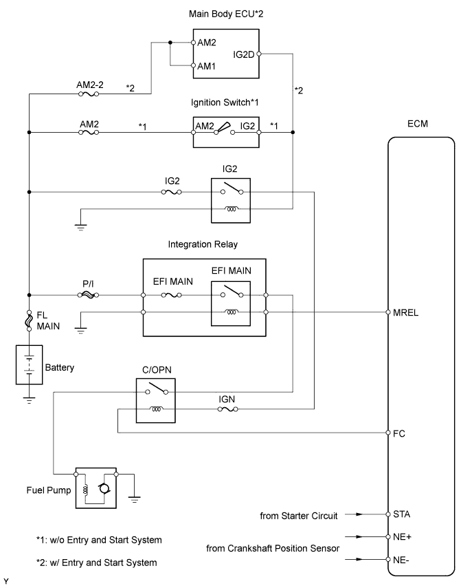
| 1.PERFORM ACTIVE TEST USING INTELLIGENT TESTER (ACTIVE THE FUEL PUMP SPEED CONTROL) |
Connect the intelligent tester to the DLC3.
Turn the ignition switch on (IG) and turn the tester ON.
Select the following menu items: Powertrain / Engine and ECT / Active Test / Control the Fuel Pump / Speed.
Check whether the fuel pump operating sound occurs when performing the Active Test on the tester.
|
| ||||
| NG | |
 |
| 2.INSPECT MAIN BODY ECU (C/OPN RELAY INPUT VOLTAGE) |
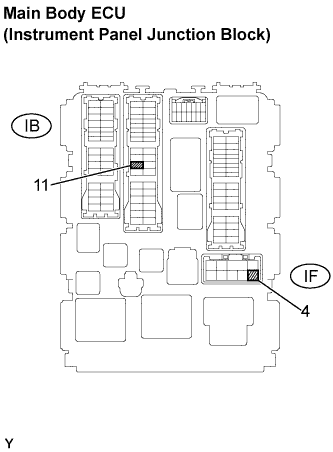 |
Measure the voltage between the terminal of the main body ECU (instrument panel junction block) and the body ground when the ignition switch is turned on (IG) and off.
| Tester Connection | Ignition Switch Condition | Specified Condition |
| IB-11 - Body ground | off | Below 1 V |
| IF-4 - Body ground | ||
| IB-11 - Body ground | on (IG) | 9 to 14 V |
| IF-4 - Body ground |
|
| ||||
| NG | |
|
| 3.CHECK HARNESS AND CONNECTOR (ENGINE ROOM NO. 1 RELAY BLOCK - MAIN BODY ECU, MAIN BODY ECU - INTEGRATION RELAY) |
Remove the IG2 relay from the engine room No. 1 relay block.
Remove the integration relay from the engine room No. 1 relay block (R/B).
Disconnect the IB and IF connectors from the main body ECU (instrument panel junction block).
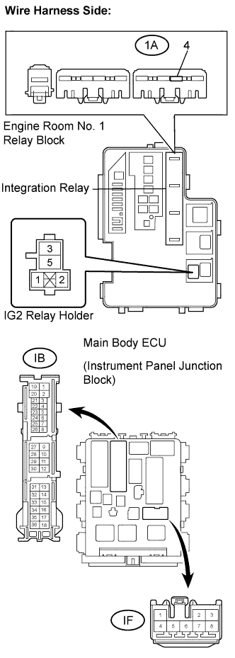 |
Measure the resistance.
| Tester Connection | Specified Condition |
| Relay Block IG2 relay block terminal (5) - IF-4 | Below 1 Ω |
| Relay Block (1A-4) - IB-11 | Below 1 Ω |
| Tester Connection | Specified Condition |
| IF-4 - Body ground | 10 kΩor higher |
| IB-11 - Body ground | 10 kΩor higher |
Reinstall the IG2 relay.
Reinstall the integration relay.
Reconnect the main body ECU (instrument panel junction block) connectors.
|
| ||||
| OK | ||
 | ||
| ||
| 4.INSPECT MAIN BODY ECU (C/OPN RELAY) |
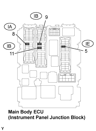 |
Remove the main body ECU (instrument panel junction block).
Measure the C/OPN relay resistance.
| Tester Connection | Specified Condition |
| IB-11 - IA-8 | 10 kΩ or higher |
| Below 1 Ω (when battery voltage is applied to terminals IB-9 and IE-5) |
Reinstall the main body ECU (instrument panel junction block).
|
| ||||
| OK | |
|
| 5.CHECK HARNESS AND CONNECTOR (MAIN BODY ECU - ECM) |
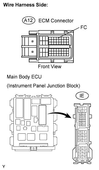 |
Disconnect the A12 ECM connector.
Disconnect the IE connector from main body ECU (instrument panel junction block).
Measure the resistance.
| Tester Connection | Specified Condition |
| IE-5 - FC (A12-7) | Below 1Ω |
| Tester Connection | Specified Condition |
| IE-5 or FC (A12-7) - Body ground | 10 kΩ or higher |
Reconnect the main body ECU (instrument panel junction block) and the ECM connectors.
|
| ||||
| OK | |
|
| 6.CHECK HARNESS AND CONNECTOR (C/OPN RELAY - FUEL PUMP - BODY GROUND) |
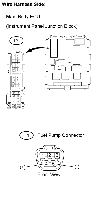 |
Check the harness and the connectors between the main body ECU (instrument panel junction block) and the fuel pump.
Disconnect the IA connector from main body ECU (instrument panel junction block).
Disconnect the T1 fuel pump connector.
Measure the resistance.
| Tester Connection | Specified Condition |
| IA-8 - Fuel pump (T1-4) | Below 1Ω |
| Tester Connection | Specified Condition |
| IA-8 or Fuel pump (T1-4) - Body ground | 10 kΩ or higher |
Check the harness and the connectors between the fuel pump and the body ground.
Disconnect the T1 fuel pump connector.
Measure the resistance.
| Tester Connection | Specified Condition |
| Fuel pump (T1-5) - Body ground | Below 1 Ω |
Reconnect the Main body ECU (instrument panel junction block) connector.
Reconnect the fuel pump connector.
|
| ||||
| OK | |
|
| 7.INSPECT FUEL PUMP |
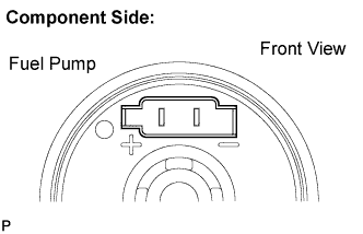 |
Inspect fuel pump resistance.
Measure the resistance between the terminals.
Inspect fuel pump operation.
Apply the battery voltage to both the terminals.
Check that the pump operates.
|
| ||||
| OK | ||
| ||
| ||
| 8.READ VALUE USING INTELLIGENT TESTER (STARTER SIGNAL) |
Connect the intelligent tester to the DLC3.
Turn the ignition switch on (IG) and turn the tester ON.
Select the following menu items: Powertrain / Engine and ECT / Data List / Starter Signal.
Check the result when the ignition switch is turned on (IG) and START.
| Ignition Switch Position | Starter Signal |
| ON | OFF |
| START | ON |
|
| ||||
| OK | |
|
| 9.READ VALUE USING INTELLIGENT TESTER (ENGINE SPEED) |
Connect the intelligent tester to the DLC3.
Turn the ignition switch on (IG) and turn the tester ON.
Select the following menu items: Powertrain / Engine and ECT / Data List / Engine Speed.
Read the values displayed on the tester while cranking.
|
| ||||
| OK | ||
| ||
| ||

