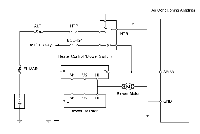
AIR CONDITIONING SYSTEM (for Manual Air Conditioning System) > Blower Motor Circuit |
| 1.INSPECT FUSE (HTR) |
Remove the HTR fuse from the engine room No. 2 relay block.
Measure the resistance of the fuse.
|
| ||||
| OK | |
 |
| 2.INSPECT HEATER RELAY (Marking: HTR) |
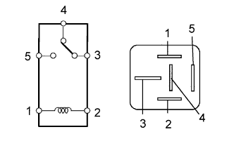 |
Remove the heater relay from the instrument panel junction block.
Measure the resistance of the relay.
| Tester Connection | Specified Condition |
| 3 - 4 | Below 1 Ω |
| 3 - 5 | 10 kΩ or higher |
| 3 - 4 | 10 kΩ or higher (when battery voltage is applied to terminals 1 and 2) |
| 3 - 5 | Below 1 Ω (when battery voltage is applied to terminals 1 and 2) |
|
| ||||
| OK | |
|
| 3.INSPECT BLOWER MOTOR |
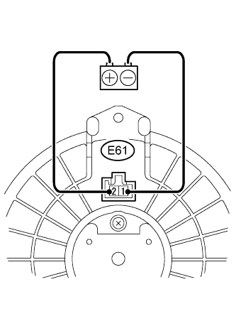 |
Disconnect the E61 motor connector.
Connect the positive (+) lead from the battery to terminal 2 and the negative (-) lead to terminal 1, then check that the blower motor operates smoothly.
Measure the current.
| Tester Connection | Condition | Specified Condition |
| E61-1 - E61-2 | Blower motor operates | 1 to 3 A |
|
| ||||
| OK | |
|
| 4.CHECK WIRE HARNESS (HEATER CONTROL (BLOWER SWITCH) - BATTERY) |
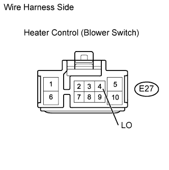 |
Disconnect the E27 heater control connector.
Measure the voltage of the wire harness side connector.
| Tester Connection | Condition | Specified Condition |
| E27-4 (LO) - Body ground | Ignition switch on (IG) | 10 to 14 V |
|
| ||||
| OK | |
|
| 5.INSPECT HEATER CONTROL (BLOWER SWITCH) |
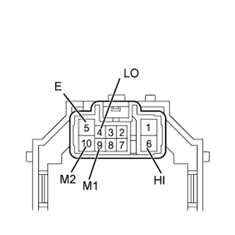 |
Remove the heater control.
Measure the resistance of the switch.
| Tester Connection | Switch Position | Specified Condition |
| ALL - 5 (E) | 0 | 10 kΩ or higher |
| 4 (LO) - 5 (E) | 1 | Below 1 Ω |
| 4 (LO) - 5 (E) - 9 (M1) | 1 to 2 | Below 1 Ω |
| 4 (LO) - 5 (E) - 9 (M1) | 2 | Below 1 Ω |
| 4 (LO) - 5 (E) - 9 (M1) - 10 (M2) | 2 to 3 | Below 1 Ω |
| 4 (LO) - 5 (E) - 10 (M2) | 3 | Below 1 Ω |
| 4 (LO) - 5 (E) - 10 (M2) - 6(HI) | 3 to 4 | Below 1 Ω |
| 4 (LO) - 5 (E) - 6 (HI) | 4 | Below 1 Ω |
|
| ||||
| OK | |
|
| 6.INSPECT BLOWER RESISTOR |
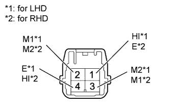 |
Remove the blower resistor.
Measure the resistance of the resistor.
| Tester Connection | Specified Condition |
| E62-4 (E) - E62-1 (HI) | 3.12 to 3.60 Ω |
| E62-4 (E) - E62-3 (M2) | 1.45 to 1.67 Ω |
| E62-4 (E) - E62-2 (M1) | 0.52 to 0.60 Ω |
| Tester Connection | Specified Condition |
| E62-1 (E) - E62-4 (HI) | 3.12 to 3.60 Ω |
| E62-1 (E) - E62-2 (M2) | 1.45 to 1.67 Ω |
| E62-1 (E) - E62-3 (M1) | 0.52 to 0.60 Ω |
|
| ||||
| OK | |
|
| 7.CHECK WIRE HARNESS (HEATER CONTROL (BLOWER SWITCH) - BLOWER RESISTOR) |
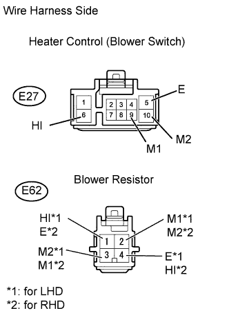 |
Disconnect the E27 heater control connector.
Disconnect the E62 blower resistor connector.
Measure the resistance of the wire harness side connectors.
| Tester Connection | Specified Condition |
| E27-6 (HI) - E62-1 (HI) | Below 1 Ω |
| E27-9 (M1) - E62-2 (M1) | Below 1 Ω |
| E27-10 (M2) - E62-3 (M2) | Below 1 Ω |
| E27-5 (E) - Body ground | Below 1 Ω |
| E62-4 (E) - Body ground | Below 1 Ω |
| Tester Connection | Specified Condition |
| E27-6 (HI) - E62-4 (HI) | Below 1 Ω |
| E27-9 (M1) - E62-3 (M1) | Below 1 Ω |
| E27-10 (M2) - E62-2 (M2) | Below 1 Ω |
| E27-5 (E) - Body ground | Below 1 Ω |
| E62-1 (E) - Body ground | Below 1 Ω |
|
| ||||
| OK | |
|
| 8.CHECK WIRE HARNESS (BLOWER RESISTOR - BLOWER MOTOR) |
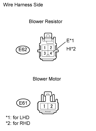 |
Disconnect the E62 blower resistor connector.
Disconnect the E61 motor connector.
Measure the resistance of the wire harness side connectors.
| Tester Connection | Specified Condition |
| E62-4 (E) - E61-1 | Below 1 Ω |
| Tester Connection | Specified Condition |
| E62-1 (E) - E61-1 | Below 1 Ω |
|
| ||||
| OK | |
|
| 9.CHECK WIRE HARNESS (BLOWER MOTOR - BODY GROUND) |
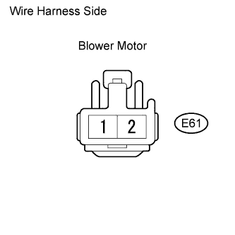 |
Disconnect the E61 motor connector.
Measure the resistance of the wire harness side connector.
| Tester Connection | Specified Condition |
| E61-2 - Body ground | Below 1 Ω |
Measure the voltage of the wire harness side connector.
| Tester Connection | Condition | Specified Condition |
| E61-2 - Body ground | Ignition switch on (IG) Heater control (blower switch) 1 | 10 to 14 V |
|
| ||||
| OK | |
|
| 10.CHECK WIRE HARNESS (AIR CONDITIONING AMPLIFIER - BATTERY) |
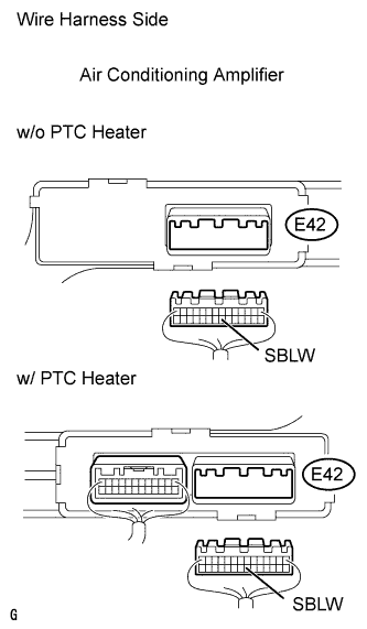 |
Disconnect the E42 amplifier connector.
Measure the voltage of the wire harness side connector.
| Tester Connection | Condition | Specified Condition |
| E42-21 (SBLW) - Body ground | Ignition switch on (IG) Heater control (blower switch): 0 | 10 to 14 V |
|
| ||||
| OK | |
|
| 11.CHECK WIRE HARNESS (AIR CONDITIONING AMPLIFIER - BODY GROUND) |
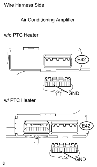 |
Disconnect the E42 amplifier connector.
Measure the resistance of the wire harness side connector.
| Tester Connection | Specified Condition |
| E42-24 (GND) - Body ground | Below 1 Ω |
|
| ||||
| OK | ||
 | ||
| ||
