 |
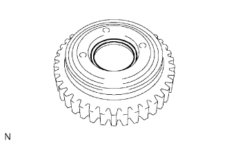
Coat an O-ring with ATF, and install it to the direct clutch drum.
- NOTICE:
- Make sure that the O-ring is not twisted or pinched when it is installed.
DIRECT CLUTCH > REASSEMBLY |
| 1. INSTALL OVERDRIVE DIRECT CLUTCH O-RING |
|
Coat an O-ring with ATF, and install it to the direct clutch drum.
| 2. INSTALL OVERDRIVE DIRECT CLUTCH DRUM SUB-ASSEMBLY |
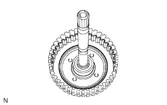 |
Coat the direct clutch drum with ATF, and install it to the intermediate shaft.
| 3. INSTALL OVERDRIVE DIRECT CLUTCH PISTON |
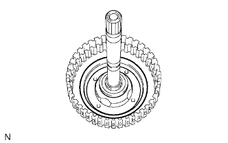 |
Coat the overdrive direct clutch piston with ATF, and install it to the direct clutch drum.
| 4. INSTALL OVERDRIVE CLUTCH RETURN SPRING SUB-ASSEMBLY |
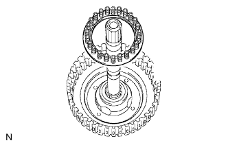 |
Install the overdrive clutch return spring to the direct clutch drum.
Coat the clutch balancer with ATF.
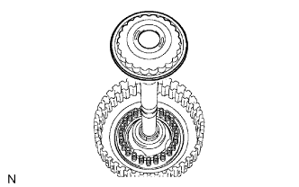 |
Install the clutch balancer to the direct clutch drum.
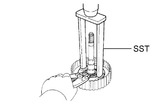 |
Place SST on the clutch balancer and compress the overdrive clutch return spring with a press.
Using a snap ring expander, install the snap ring to the direct clutch drum.
Make sure that the end gap of the snap ring is not aligned with the spring retainer claw.
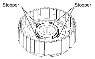 |
Set the end gap of the snap ring in the piston as shown in the illustration.
| 5. INSTALL OVERDRIVE DIRECT CLUTCH DISC |
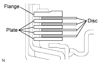 |
Coat the 4 discs with ATF.
Install the 4 plates, 4 discs and flange to the intermediate shaft.
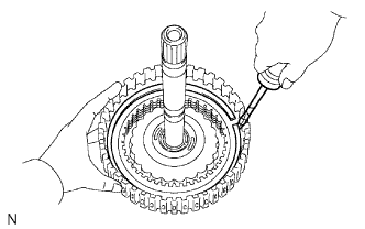 |
Using a screwdriver, install the snap ring.
Check that the end gap of the snap ring is not aligned with one of the cutouts.
| 6. INSTALL DIRECT MULTIPLE DISC CLUTCH DISC |
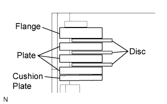 |
Coat the 3 discs with ATF.
Install the cushion plate, 3 plates, 3 discs and flange to the intermediate shaft.
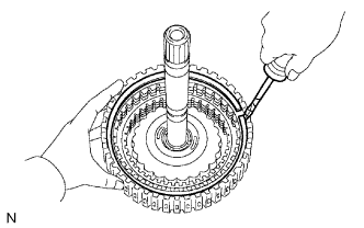 |
Using a screwdriver, install the snap ring.
Check that the end gap of the snap ring is not aligned with one of the cutouts.
| 7. INSPECT PACK CLEARANCE OF DIRECT CLUTCH AND OVERDRIVE CLUTCH |
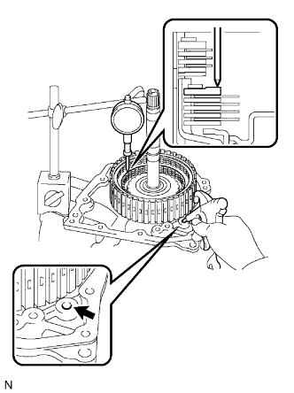 |
Using a dial indicator, measure the direct clutch and overdrive clutch pack clearance while applying and releasing compressed air (392 kPa, 4.0 kgf/cm2, 57 psi).
| No. | Thickness | No. | Thickness |
| 0 | 2.5 mm (0.098 in.) | 4 | 2.9 mm (0.114 in.) |
| 1 | 2.6 mm (0.102 in.) | 5 | 3.0 mm (0.118 in.) |
| 2 | 2.7 mm (0.106 in.) | 6 | 3.1 mm (0.122 in.) |
| 3 | 2.8 mm (0.110 in.) | - | - |
| 8. INSPECT PACK CLEARANCE OF REVERSE CLUTCH |
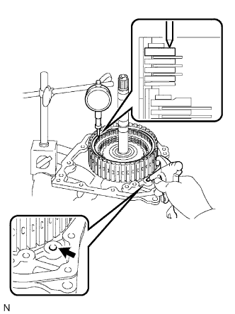 |
Install the intermediate shaft onto the transaxle rear cover.
Using a dial indicator, measure the direct clutch pack clearance while applying and releasing compressed air (392 kPa, 4.0 kgf/cm2, 57 psi).
| No. | Thickness | No. | Thickness |
| 1 | 3.0 mm (0.118 in.) | 5 | 3.4 mm (0.134 in.) |
| 2 | 3.1 mm (0.122 in.) | 6 | 3.5 mm (0.138 in.) |
| 3 | 3.2 mm (0.126 in.) | 7 | 3.6 mm (0.142 in.) |
| 4 | 3.3 mm (0.130 in.) | - | - |
| 9. INSPECT DIRECT CLUTCH ASSEMBLY |
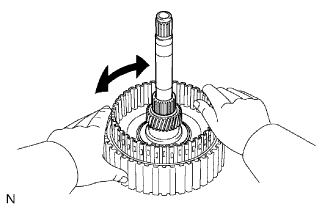 |
Check that the disc rotates after inserting the rear planetary sun gear.