 |
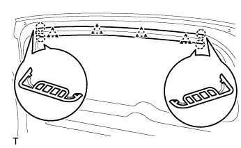
Using a screwdriver, detach the 4 claws and 4 clips and remove the garnish.
- HINT:
- Tape the screwdriver tip before use.
BACK DOOR > DISASSEMBLY |
| 1. DISCONNECT CABLE FROM NEGATIVE BATTERY TERMINAL |
| 2. REMOVE BACK DOOR CENTER GARNISH |
|
Using a screwdriver, detach the 4 claws and 4 clips and remove the garnish.
| 3. REMOVE BACK DOOR SIDE GARNISH LH |
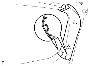 |
Using a screwdriver, detach the 2 claws and 2 clips and remove the garnish.
| 4. REMOVE BACK DOOR SIDE GARNISH RH |
| 5. REMOVE BACK DOOR COURTESY LIGHT ASSEMBLY |
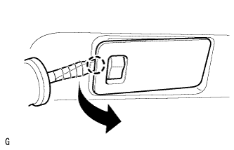 |
Using a screwdriver, pry out the light as shown in the illustration.
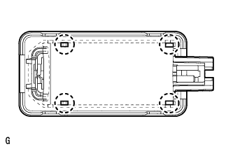 |
Detach the 4 claws and remove the light shade.
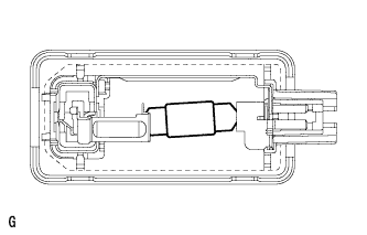 |
Remove the light bulb from the light.
| 6. REMOVE BACK DOOR TRIM BOARD ASSEMBLY |
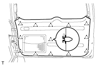 |
Using a screwdriver, detach the 13 clips and remove the trim board.
Remove the 5 screws and the back door trim pocket.
| 7. REMOVE REAR WIPER ARM AND BLADE ASSEMBLY |
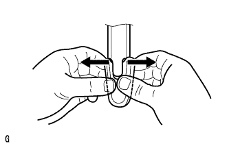 |
Widen each end of the cap 5 mm (0.19in).
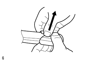 |
Lift the both widened ends of the cap.
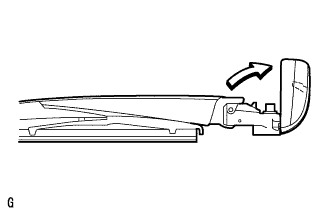 |
Rotate the cap. Fix the cap in place.
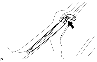 |
Remove the nut and arm and blade.
| 8. REMOVE REAR SPOILER |
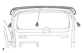 |
Remove the 3 bolts.
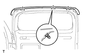 |
Remove the 3 clips and spoiler.
Disconnect the center stop light connector and remove the rear spoiler.
| 9. REMOVE CENTER STOP LIGHT ASSEMBLY |
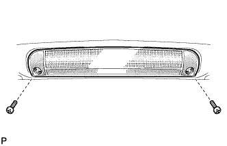 |
Disconnect the connector.
Remove the 2 screws and center stop light.
| 10. REMOVE SPARE WHEEL CARRIER BRACKET SUB-ASSEMBLY (w/ Tire Carrier) |
w/o Breakaway Bolt:
Remove the spare wheel carrier bracket.
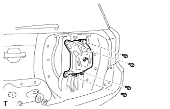 |
Remove the 4 bolts.
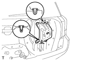 |
Detach the 2 clips and remove the carrier bracket.
 |
w/ Breakaway Bolt:
Remove the spare wheel carrier bracket.
Using a centering punch, mark the center of the 2 breakaway bolts.
Using a 3 to 4 mm (0.12 to 0.16 in.) drill, drill a hole in the 2 breakaway bolts heads.
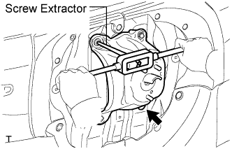
Using a screw extractor, remove the 2 breakaway bolts.
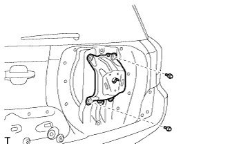 |
Remove the 2 bolts.
|
Detach the 2 clips and remove the carrier bracket.
| 11. REMOVE LOWER BACK DOOR OUTSIDE GARNISH SUB-ASSEMBLY LH (w/ Tire Carrier) |
Put protective tape around the back door outside garnish.
Remove the screw.
Remove the back door outside garnish.
Using a moulding remover, detach the clips and remove the back door outside garnish.
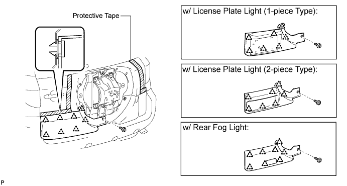
w/ License Plate Light:
Disconnect the license plate light connector.
w/ Rear Fog Light:
Disconnect the rear fog light connector.
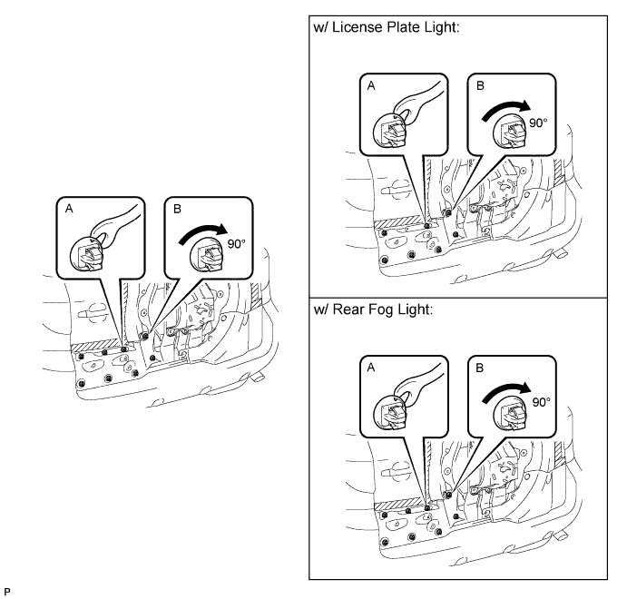
Remove the clips from the back door panel.
Using a clip remover, remove the clip labeled A.
Turn the remaining clips 90° as shown in the part of the illustration labeled B, and remove them.
| 12. REMOVE BACK DOOR GARNISH COVER (for 1-piece Type) |
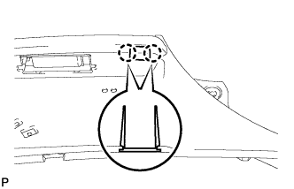 |
Detach the 2 claws and remove the back door garnish cover.
| 13. REMOVE LICENSE PLATE LIGHT ASSEMBLY (w/ License Plate Light) |
Disconnect the connector.
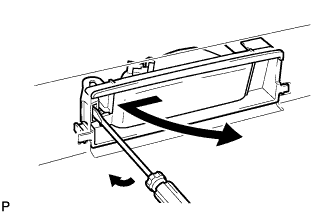 |
Using a screwdriver, remove the light as shown in the illustration.
| 14. REMOVE REAR FOG LIGHT ASSEMBLY (w/ Rear Fog Light) |
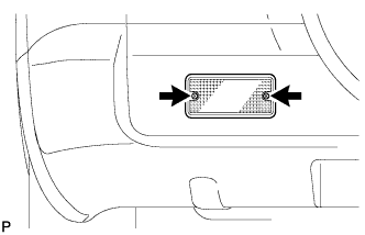 |
Remove the 2 screws and rear fog light.
Disconnect the connector.
| 15. REMOVE UPPER BACK DOOR OUTSIDE GARNISH SUB-ASSEMBLY LH (w/ Tire Carrier) |
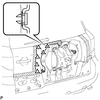 |
Remove the screw.
Using a moulding remover, detach the 6 clips and remove the back door outside garnish.
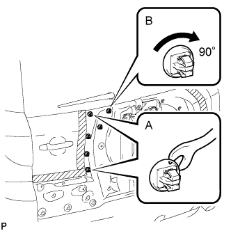 |
Using a clip remover, remove the 2 clips labeled A.
Turn the remaining clips 90° as shown in the part of the illustration labeled B, and remove them.
| 16. REMOVE LOWER BACK DOOR OUTSIDE GARNISH SUB-ASSEMBLY RH (w/ Tire Carrier) |
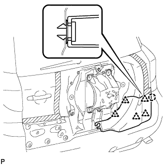 |
Detach the 5 clips and claw, and remove the back door outside garnish.
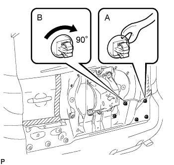 |
Using a clip remover, remove the clip labeled A.
Turn the remaining clips 90° as shown in the part of the illustration labeled B, and remove them.
| 17. REMOVE UPPER BACK DOOR OUTSIDE GARNISH SUB-ASSEMBLY RH (w/ Tire Carrier) |
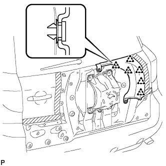 |
Detach the 6 clips and remove the back door outside garnish.
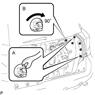 |
Using a clip remover, remove the 2 clips labeled A.
Turn the remaining clips 90° as shown in the part of the illustration labeled B, and remove them.
| 18. REMOVE BACK DOOR OUTSIDE GARNISH SUB-ASSEMBLY (w/o Tire Carrier) |
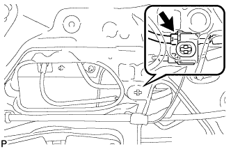 |
Disconnect the connector.
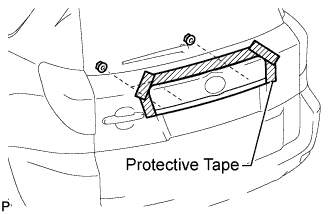 |
Put protective tape around the back door outside garnish.
Remove the 3 nuts.
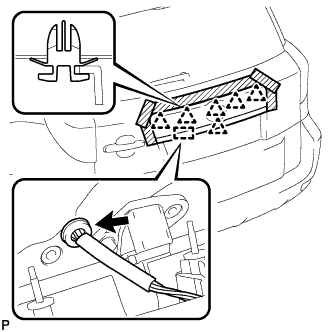 |
Detach the grommet and 5 clips, and remove the back door outside garnish.
| 19. REMOVE LICENSE PLATE LIGHT ASSEMBLY (w/o Tire Carrier) |
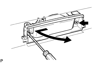 |
Disconnect the connector.
Remove the screw.
Using a screwdriver, remove the light as shown in the illustration.
| 20. REMOVE TELEVISION CAMERA ASSEMBLY (w/ Parking Assist Monitor System) |
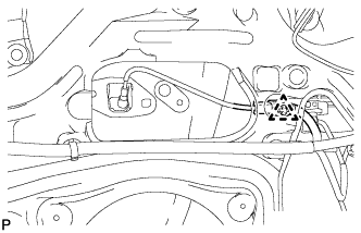 |
Disconnect the television camera connector and detach the clamp.
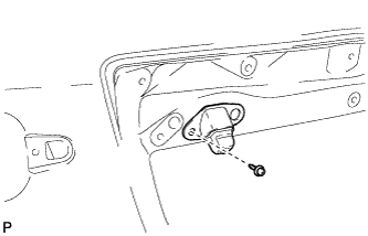 |
Remove the screw and television camera.
| 21. REMOVE LOWER BACK DOOR OUTSIDE GARNISH SUB-ASSEMBLY (w/o Tire Carrier) |
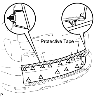 |
Put protective tape around the back door outside garnish.
Detach the 15 clips and claw, and remove the back door outside garnish.
| 22. REMOVE BACK DOOR OUTSIDE GARNISH CLIP (w/o Tire Carrier) |
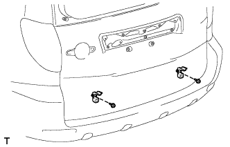 |
Remove the 2 screws and 2 clips.
| 23. REMOVE REAR WIPER MOTOR ASSEMBLY |
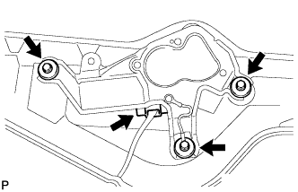 |
Disconnect the connector.
Remove the 3 bolts and wiper motor.
| 24. REMOVE BACK DOOR SERVICE HOLE COVER |
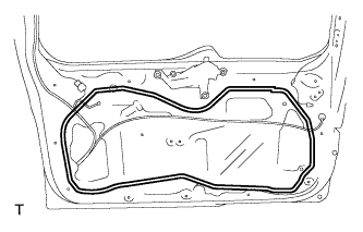 |
Disconnect each connector and remove the service hole cover.
| 25. REMOVE BACK DOOR LOCK ASSEMBLY |
Disconnect the connector.
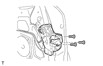 |
Using a T30 "TORX" socket, remove the 3 screws.
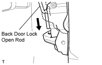 |
Slide the door lock downward to disconnect the back door lock open rod from the door lock. Then remove the door lock.
| 26. REMOVE BACK DOOR OUTSIDE HANDLE COVER |
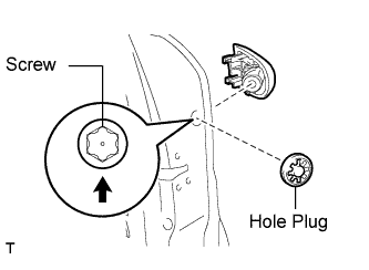 |
Remove the hole plug.
Using a T30 "TOX" socket, loosen the screw and remove the cover.
| 27. REMOVE BACK DOOR OUTSIDE HANDLE |
w/ Entry and Start System:
Disconnect the connector.
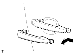 |
Remove the handle by sliding and pulling it in the direction indicated by the arrow in the illustration.
| 28. REMOVE DOOR OUTSIDE HANDLE PAD |
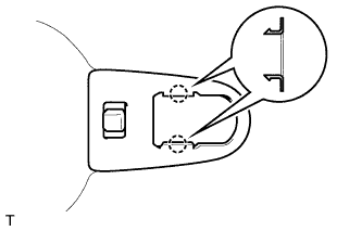 |
Detach the 2 claws and remove the pad.
| 29. REMOVE BACK DOOR REAR OUTSIDE HANDLE PAD |
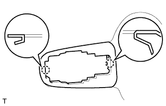 |
Detach the 2 claws and remove the pad.
| 30. REMOVE BACK DOOR OUTSIDE HANDLE FRAME SUB-ASSEMBLY |
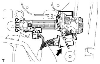 |
w/ Entry and Start System:
Disconnect the connector and clamp.
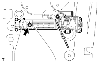 |
Using a T30 "TORX" socket, loosen the screw of the frame.
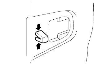 |
Using pliers, pinch the clip.
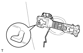 |
Detach the claw and remove the frame.
Remove the front door lock open rod.
| 31. REMOVE DOOR ELECTRICAL KEY OSCILLATOR (w/ Entry and Start System) |
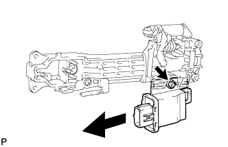 |
Remove the screw and door electrical key oscillator.
| 32. REMOVE BACK DOOR CHECK ASSEMBLY |
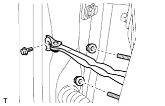 |
Remove the bolt, 2 nuts and door check.
| 33. REMOVE BACK DOOR SIDE FEMALE STOPPER |
Remove the 2 bolts and stopper.
| 34. REMOVE CUSHION |
Remove the 2 cushions.
| 35. REMOVE STOPPER |