AIR FUEL RATIO SENSOR > INSTALLATION |
| 1. INSTALL AIR FUEL RATIO SENSOR (for Bank 1) |
![]() |
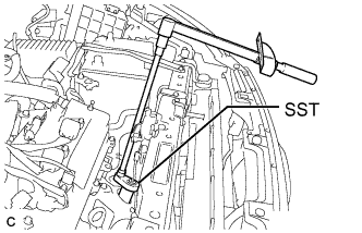
Using SST, install the air fuel ratio sensor (for bank 1).
| 2. INSTALL EXHAUST MANIFOLD SUB-ASSEMBLY RH (for Bank 1) |
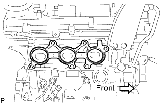
![]() |
Install a new gasket as shown in the illustration.
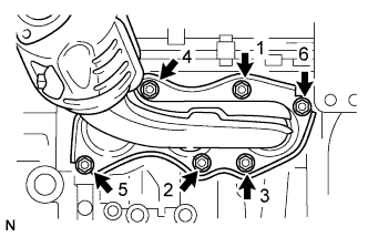
![]() |
Install the manifold with the 6 nuts in the order shown in the illustration.
| 3. INSTALL MANIFOLD STAY (for Bank 1) |
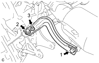
![]() |
Install the manifold stay with the 2 bolts and nut in the order shown in the illustration.
| 4. INSTALL PROPELLER WITH CENTER BEARING SHAFT ASSEMBLY (for Bank 1) |
| 5. INSTALL FRONT EXHAUST PIPE ASSEMBLY (for Bank 1) |
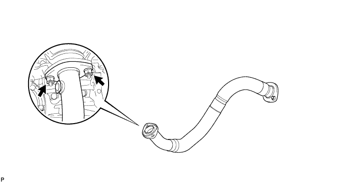
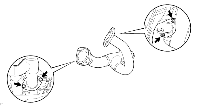
Install a new gasket.
Install the front exhaust pipe assembly with the 2 nuts.

| 6. INSTALL NO. 1 FRONT EXHAUST PIPE SUPPORT BRACKET (for Bank 1) |
Install the No. 1 exhaust pipe support bracket with the 2 bolts.
| 7. INSTALL CENTER EXHAUST PIPE ASSEMBLY (for Bank 1) |
Install 2 new gaskets.
Install the center exhaust pipe assembly with the 2 bolts and 2 nuts.

| 8. INSTALL NO. 2 EXHAUST PIPE SUB-ASSEMBLY (for Bank 1) |
![]() |
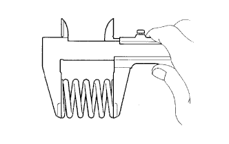
Using a vernier caliper, measure the free length of the compression spring.
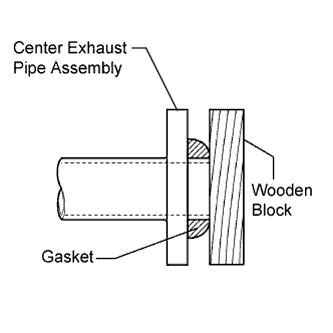
Fully insert a new gasket to the center exhaust pipe assembly.
![]() |
Using a plastic hammer and wooden block, tap in the new gasket until its surface is flush with the center exhaust pipe assembly.
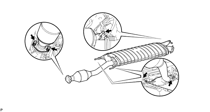
Connect the No. 2 exhaust pipe sub-assembly to the 3 exhaust pipe supports.
Install the No. 2 exhaust pipe sub-assembly with the 2 bolts and 2 compression springs.

| 9. INSTALL AIR FUEL RATIO SENSOR (for Bank 2) |
![]() |
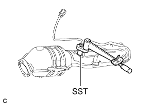
Using SST, install the air fuel ratio sensor (for bank 2).
Connect the sensor connector.
| 10. INSPECT FOR EXHAUST GAS LEAK |