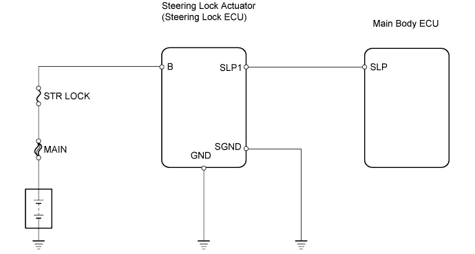
STEERING LOCK SYSTEM > Unlock Position Sensor Signal Circuit |
| 1.CHECK STEERING LOCK ACTUATOR |
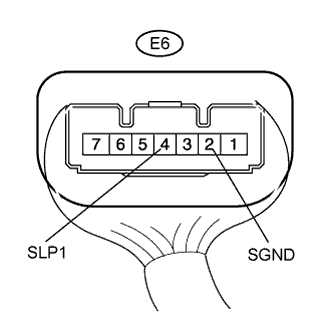 |
Measure the voltage of the steering lock actuator.
| Tester Connection | Condition (Steering Lock position) | Specified Condition |
| E6-4 (SLP1) - E6-2 (SGND) | When locked | 11 to 14 V |
| E6-4 (SLP1) - E6-2 (SGND) | When unlocked | Below 1.2 V |
|
| ||||
| NG | |
 |
| 2.CHECK WIRE HARNESS (STEERING LOCK ACTUATOR - BODY GROUND) |
 |
Disconnect the E6 steering lock actuator connector.
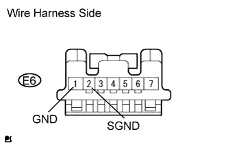
Measure the resistance of the wire harness side connector.
| Tester Connection | Specified Condition |
| E6-1 (GND) - Body ground | Below 1 Ω |
| E6-2 (SGND) - Body ground | Below 1 Ω |
|
| ||||
| OK | |
|
| 3.CHECK WIRE HARNESS (BATTERY - STEERING LOCK ACTUATOR) |
 |
Disconnect the E6 steering lock actuator connector.
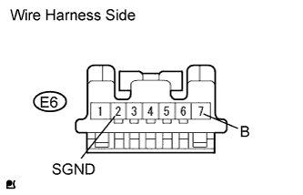
Measure the voltage of the wire harness side connector.
| Tester Connection | Specified Condition |
| E6-7 (B) - E6-2 (SGND) | 11 to 14 V |
|
| ||||
| OK | |
|
| 4.CHECK WIRE HARNESS (STEERING LOCK ACTUATOR - MAIN BODY ECU) |
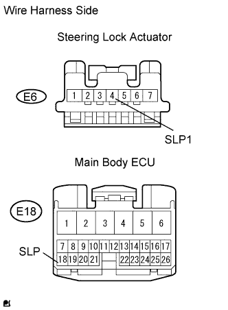 |
Disconnect the E6 steering lock actuator connector.
Disconnect the E18 main body ECU connector.
Measure the resistance of the wire harness side connectors.
| Tester Connection | Specified Condition |
| E18-18 (SLP) - E6-4 (SLP1) | Below 1 Ω |
| E6-4 (SLP1) - Body ground | Below 1 Ω |
|
| ||||
| OK | ||
 | ||
| ||

