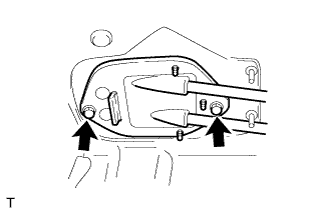
 |
Install the retainer with the 2 bolts.
- Torque:
- 5.0 N*m{ 51 kgf*cm , 44 in.*lbf }
TRANSMISSION CONTROL CABLE > INSTALLATION |
| 1. INSTALL TRANSAXLE CONTROL CABLE ASSEMBLY |
|
Install the retainer with the 2 bolts.
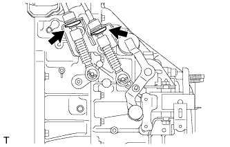 |
Connect the 2 cables to the control cable bracket with 2 new clips.
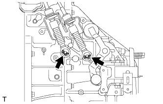 |
Connect the 2 cables to the transaxle and install the 2 clips.
| 2. CONNECT TRANSAXLE CONTROL CABLE ASSEMBLY |
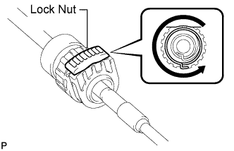 |
Connect the ends of the control cable and install the 2 clips to the shift lever.
Turn the lock nuts of the shift cable 270° counterclockwise, and hold them in that position.
Install the shift cable while holding them.
Check that the cables are installed securely.
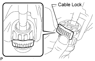 |
Push in the cable locks of the shift cable and select cable.
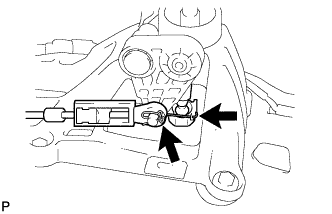 |
Connect the cable ends of the control cable and install the 2 clips.
| 3. ADJUST TRANSMISSION CONTROL CABLE ASSEMBLY |
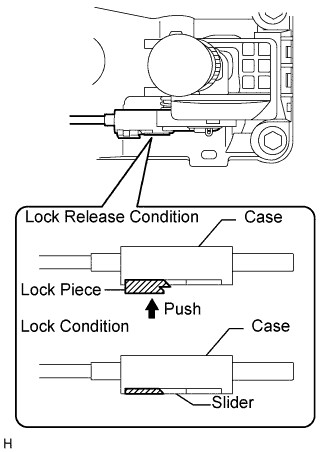 |
To release the lock (lock condition to lock release condition).
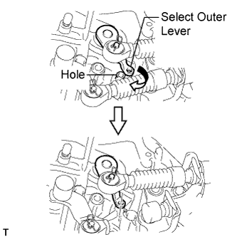 |
Align the hole of the select outer lever with the hole in the transmission.
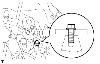 |
Insert a bolt into the aligned holes to fix the select outer lever in place.
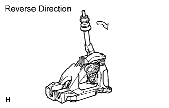 |
Turn the shift lever in the reverse direction without pulling up the slider shaft.
|
While holding the shift lever in the reverse direction, lock the cable length adjustment mechanism of the select cable.
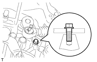 |
Remove the bolt to free the select outer lever.
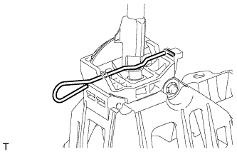 |
for new shift lever:
Remove the stopper pin and dispose of it.
| 4. INSTALL REAR CONSOLE BOX SUB-ASSEMBLY |
Connect the connector.
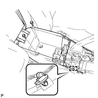 |
Install the rear console box with the 2 bolts and attach the wire harness clamp.
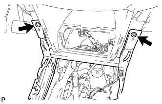 |
Install the 2 screws.
| 5. INSTALL CONSOLE REAR END PANEL |
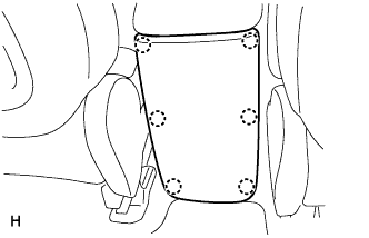 |
Attach the 6 claws to install the console rear end panel.
| 6. INSTALL UPPER REAR CONSOLE PANEL SUB-ASSEMBLY |
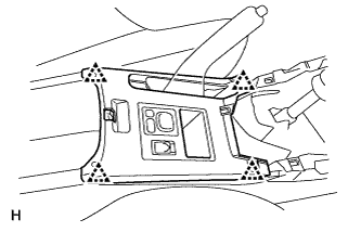 |
Connect the connectors.
Attach the 4 clips to install the upper rear console panel.
| 7. INSTALL CONSOLE CUP HOLDER BOX |
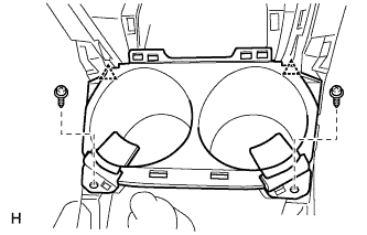 |
Attach the 2 clips to install the cup holder box.
Install the 2 screws.
| 8. INSTALL SWITCH BASE |
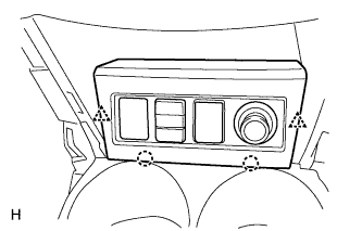 |
Connect the connectors.
Attach the 2 clips and 2 claws to install the switch base.
| 9. INSTALL UPPER CONSOLE PANEL SUB-ASSEMBLY |
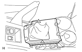 |
Attach the 2 clips and 4 claws to install the upper console panel.
| 10. INSTALL SHIFT LEVER KNOB SUB-ASSEMBLY |
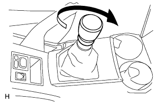 |
for Manual Transaxle:
Twist the shift lever knob in the direction indicated by the arrow to install it.
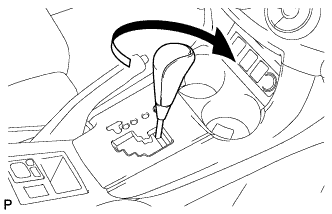 |
for Automatic Transaxle:
Twist the shift lever knob in the direction indicated by the arrow to install it.
| 11. INSTALL NO. 2 CONSOLE UPPER PANEL GARNISH |
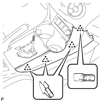 |
Attach the 4 clips to install the upper panel garnish.
| 12. INSTALL NO. 1 CONSOLE UPPER PANEL GARNISH |
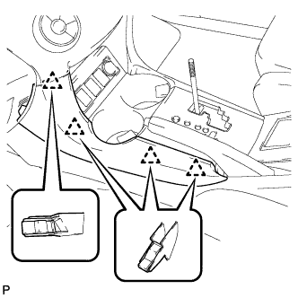 |
Attach the 4 clips to install the upper panel garnish.
| 13. INSTALL AIR CLEANER CASE |
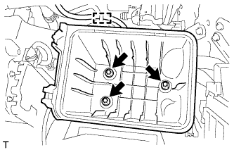 |
Install the air cleaner case with the 3 bolts.
Attach the wire harness clamp to the air cleaner case.
| 14. INSTALL AIR CLEANER CAP SUB-ASSEMBLY |
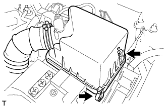 |
Insert the hinge part of the air cleaner cap and hose into the air cleaner case, and then fasten the 2 hook clamps.
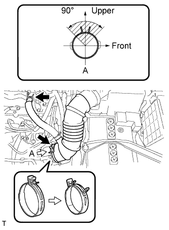 |
Connect the No. 1 air cleaner hose to the throttle body and push apart the tabs of the No. 1 air cleaner hose clamp.
Connect the No. 2 ventilation hose to the cylinder head cover.
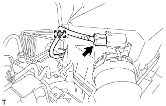 |
Attach the clamp.
Connect the mass air flow meter connector.
| 15. INSTALL NO. 2 CYLINDER HEAD COVER |
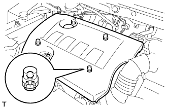 |
Attach the 4 clips to install the cover.