Remove the gasket from the exhaust manifold.
DIFFERENTIAL OIL SEAL > REPLACEMENT |
| 1. DRAIN TRANSAXLE OIL |
Remove the filler plug and gasket.
Remove the drain plug and gasket, and then drain the manual transaxle oil.
Install a new gasket and the drain plug.
| 2. REMOVE FRONT WHEEL |
| 3. REMOVE NO. 1 ENGINE UNDER COVER |
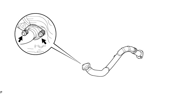
| 4. REMOVE FRONT EXHAUST PIPE |
Remove the 2 bolts, 2 compression springs and front exhaust pipe.
Remove the gasket from the exhaust manifold.
| 5. REMOVE FRONT SPEED SENSOR LH |
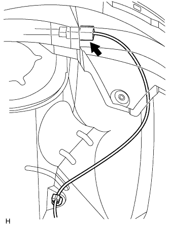 |
Disconnect the sensor connector.
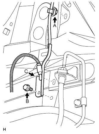 |
Remove the sensor clip (labeled A), bolt (labeled B) and sensor clamp (labeled C).
Remove the sensor clip (labeled D), bolt (labeled E) and sensor clamp (labeled F).
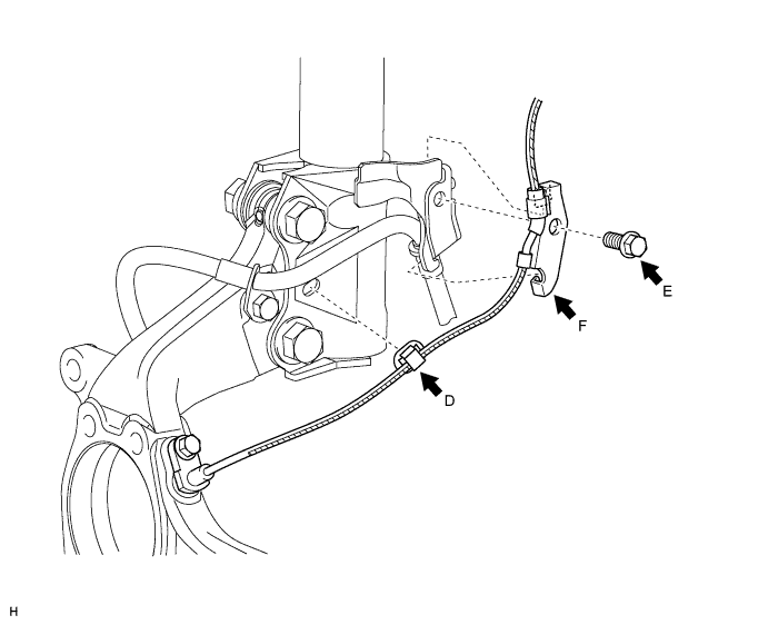
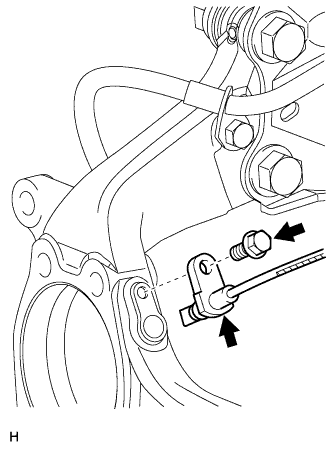 |
Remove the bolt and sensor from the knuckle.
| 6. REMOVE FRONT SPEED SENSOR RH |
| 7. DISCONNECT FRONT STABILIZER LINK ASSEMBLY LH |
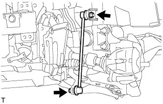 |
Remove the 2 nuts and stabilizer link.
| 8. DISCONNECT FRONT STABILIZER LINK ASSEMBLY RH |
| 9. DISCONNECT FRONT SUSPENSION NO. 1 LOWER ARM SUB-ASSEMBLY LH |
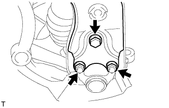 |
Remove the bolt and 2 nuts.
Disconnect the lower arm from the ball joint.
| 10. DISCONNECT FRONT SUSPENSION NO. 1 LOWER ARM SUB-ASSEMBLY RH |
| 11. REMOVE FRONT DRIVE SHAFT ASSEMBLY LH |
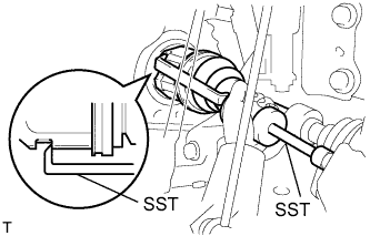 |
Using SST, remove the front drive shaft.
| 12. REMOVE FRONT DRIVE SHAFT ASSEMBLY RH |
| 13. REMOVE TRANSAXLE CASE OIL SEAL LH |
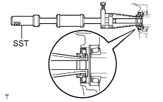 |
Using SST, tap out the transaxle case oil seal.
| 14. REMOVE TRANSAXLE CASE OIL SEAL RH |
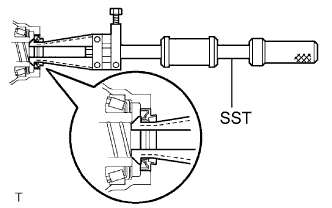 |
Using SST, tap out the transaxle case oil seal.
| 15. INSTALL TRANSAXLE CASE OIL SEAL LH |
Coat the lip of a new oil seal with MP grease.
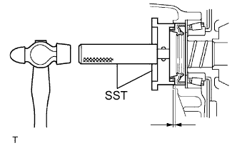 |
Using SST and a hammer, tap in the oil seal.
| 16. INSTALL TRANSAXLE CASE OIL SEAL RH |
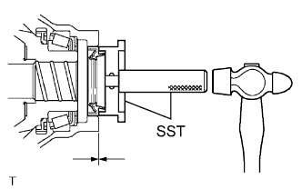 |
Coat the lip of a new transaxle case oil seal with MP grease.
Using SST and a hammer, tap in the oil seal.
| 17. INSTALL FRONT DRIVE SHAFT ASSEMBLY LH |
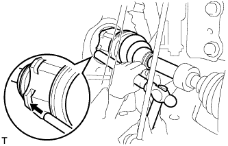 |
Coat the splines of the inboard joint shaft with gear oil.
Align the shaft splines and tap in the drive shaft with a brass bar and hammer.
| 18. INSTALL FRONT DRIVE SHAFT ASSEMBLY RH |
| 19. CONNECT FRONT SUSPENSION NO. 1 LOWER ARM SUB-ASSEMBLY LH |
Connect the lower arm to the ball joint with the 2 bolts and nut.
| 20. CONNECT FRONT SUSPENSION NO. 1 LOWER ARM SUB-ASSEMBLY RH |
| 21. CONNECT FRONT STABILIZER LINK ASSEMBLY LH |
Install the link with the 2 nuts.
| 22. INSTALL FRONT STABILIZER LINK ASSEMBLY RH |
| 23. INSTALL FRONT SPEED SENSOR LH |
|
Set the sensor into the knuckle, and then install the sensor with the bolt.
Install the sensor clamp and sensor clip as follows.
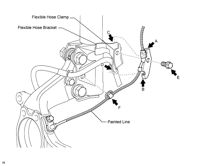
Simultaneously perform the following: 1) hang the hook part of the sensor clamp (labeled A) on the part of the flexible hose bracket (labeled C); and 2) insert the hook part of the sensor clamp (labeled B) to the part of the flexible hose bracket (labeled D).
Install the sensor clamp to the flexible hose clamp and flexible hose bracket with the bolt (labeled E).
Insert the sensor clip (labeled F) into the hole on the absorber lower bracket.
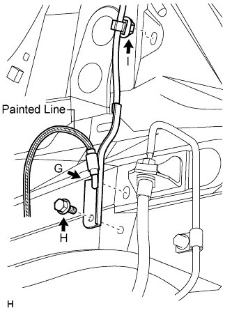 |
Install the sensor clamp and sensor clip as follows.
Set the sensor clamp (labeled G) on the side member, and then install the bolt (labeled H).
Insert the sensor clip (labeled I) into the hole on the apron.
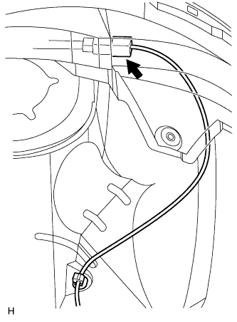 |
Connect the sensor connector.
| 24. INSTALL FRONT SPEED SENSOR RH |
| 25. INSTALL FRONT EXHAUST PIPE |
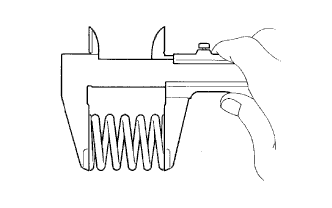 |
Using a vernier caliper, measure the free length of the compression spring.
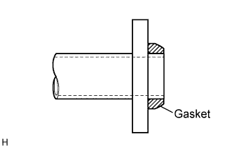 |
Install a new gasket by hand so that its surface is flush with the exhaust manifold.
Install the front exhaust pipe with the 2 compression springs and 2 bolts.
| 26. INSTALL NO. 1 ENGINE UNDER COVER |
| 27. INSTALL FRONT WHEEL |
| 28. ADD TRANSAXLE OIL |
| 29. INSPECT MANUAL TRANSAXLE OIL |
Inspect manual transaxle (Click here).
| 30. INSPECT FRONT WHEEL ALIGNMENT |