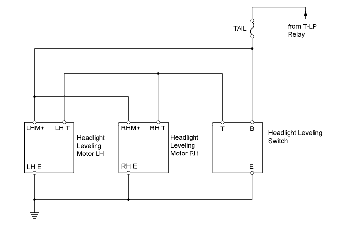
LIGHTING SYSTEM > Headlight Beam Level Control Actuator Circuit |
| 1.CHECK TAILLIGHT |
Check that the taillight comes on when the light control switch is turned on (TAIL).
|
| ||||
| OK | |
 |
| 2.CHECK WIRE HARNESS (BATTERY - INSTRUMENT PANEL JUNCTION BLOCK) |
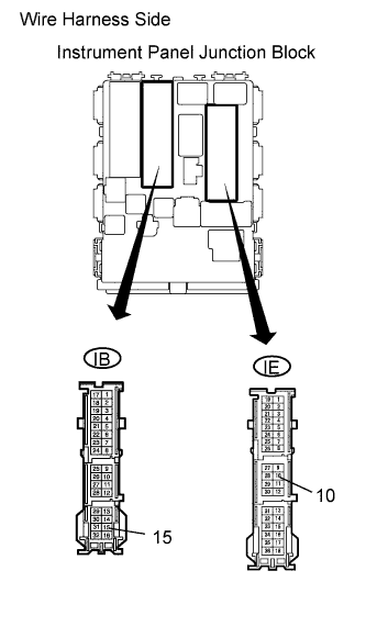 |
Disconnect the IE and IB instrument panel junction block connectors.
Measure the voltage of the wire harness side connectors.
| Tester Connection | Condition | Specified Condition |
| IE-10 - Body ground | Light control switch TAIL | 11 to 14 V |
| IB-15 - Body ground | Light control switch TAIL | 11 to 14 V |
|
| ||||
| OK | |
|
| 3.CHECK WIRE HARNESS (INSTRUMENT PANEL JUNCTION BLOCK - HEADLIGHT LEVELING SWITCH) |
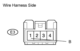 |
Disconnect the E3 headlight leveling switch connector.
Measure the voltage of the wire harness side connector.
| Tester Connection | Condition | Specified Condition |
| E3-1 (B) - Body ground | Light control switch TAIL | 11 to 14 V |
|
| ||||
| OK | |
|
| 4.INSPECT HEADLIGHT LEVELING SWITCH |
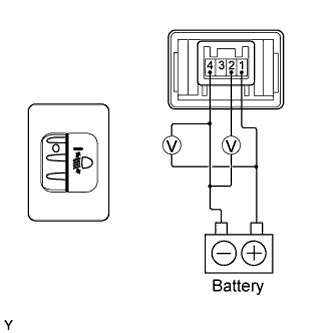 |
Remove the headlight leveling switch.
Connect the positive (+) battery lead to terminal 1 and the negative (-) battery lead to terminal 4.
Check the ratio which is obtained by dividing the voltage between terminals 2 and 4 by the voltage between 1 and 4. The voltages must be measured using a voltmeter.
| Tester Connection | Switch Position | Specified Condition |
| 1 (B) - 4 (E) and 2 (T) - 4 (E) | 0 | 0.87 to 0.93 |
| 1 (B) - 4 (E) and 2 (T) - 4 (E) | 1 | 0.76 to 0.82 |
| 1 (B) - 4 (E) and 2 (T) - 4 (E) | 2 | 0.66 to 0.72 |
| 1 (B) - 4 (E) and 2 (T) - 4 (E) | 3 | 0.55 to 0.61 |
| 1 (B) - 4 (E) and 2 (T) - 4 (E) | 4 | 0.44 to 0.50 |
| 1 (B) - 4 (E) and 2 (T) - 4 (E) | 5 | 0.34 to 0.40 |
|
| ||||
| OK | |
|
| 5.CHECK WIRE HARNESS (LEVELING SWITCH - LEVELING MOTOR AND BODY GROUND) |
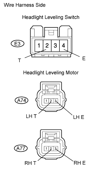 |
w/ Hood Moulding:
Disconnect the E3 headlight leveling switch connector.
Disconnect the A74 and A77 headlight leveling motor connectors.
Measure the resistance of the wire harness side connectors.
| Tester Connection | Specified Condition |
| E3-2 (T) - A74-2 (LH T) | Below 1 Ω |
| E3-2 (T) - Body ground | 10 kΩ or higher |
| E3-2 (T) - A77-2 (RH T) | Below 1 Ω |
| E3-2 (T) - Body ground | 10 kΩ or higher |
| E3-4 (E) - Body ground | Below 1 Ω |
| A74-3 (LH E) - Body ground | Below 1 Ω |
| A77-3 (RH E) - Body ground | Below 1 Ω |
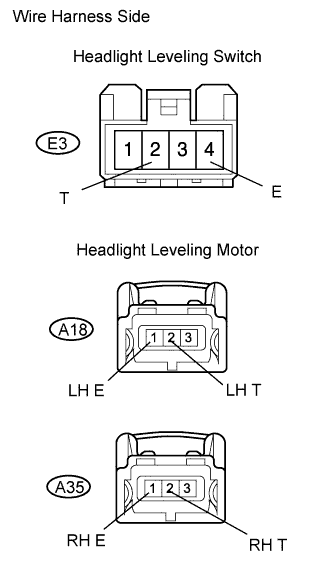 |
w/o Hood Moulding:
Disconnect the E3 headlight leveling switch connector.
Disconnect the A18 and A35 headlight leveling motor connectors.
Measure the resistance of the wire harness side connectors.
| Tester Connection | Specified Condition |
| E3-2 (T) - A18-2 (LH T) | Below 1 Ω |
| E3-2 (T) - Body ground | 10 kΩ or higher |
| E3-2 (T) - A35-2 (RH T) | Below 1 Ω |
| E3-2 (T) - Body ground | 10 kΩ or higher |
| E3-4 (E) - Body ground | Below 1 Ω |
| A18-1 (LH E) - Body ground | Below 1 Ω |
| A35-1 (RH E) - Body ground | Below 1 Ω |
|
| ||||
| OK | |
|
| 6.CHECK WIRE HARNESS (INSTRUMENT PANEL JUNCTION BLOCK - LEVELING MOTOR) |
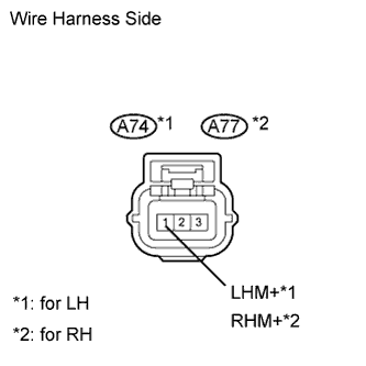 |
w/ Hood Moulding:
Disconnect the A74 and A77 headlight leveling motor connectors.
Measure the voltage of the wire harness side connectors.
| Tester Connection | Condition | Specified Condition |
| A74-1 (LHM+) - Body ground | Light control switch TAIL | 11 to 14 V |
| A77-1 (RHM+) - Body ground | Light control switch TAIL | 11 to 14 V |
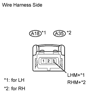 |
w/o Hood Moulding:
Disconnect the A18 and A35 headlight leveling motor connectors.
Measure the voltage of the wire harness side connectors.
| Tester Connection | Condition | Specified Condition |
| A18-3 (LHM+) - Body ground | Light control switch TAIL | 11 to 14 V |
| A35-3 (RHM+) - Body ground | Light control switch TAIL | 11 to 14 V |
|
| ||||
| OK | ||
 | ||
| ||
