METER / GAUGE SYSTEM > ON-VEHICLE INSPECTION |
| 1. CHECK SPEEDOMETER |
Check the operation.
Connect the intelligent tester to the DLC3 connector.
Turn the ignition switch ON.
Turn the intelligent tester on.
Enter the following menus : Powertrain / Engine and ECT / Data List.
According to the display on intelligent tester, read the Data List.
| Intelligent tester display | Speedometer display Data in ( ) is for reference |
| 20 km/h | (21 to 25 km/h) |
| 40 km/h | 41.7 to 46.2 km/h |
| 60 km/h | 62.7 to 67.2 km/h |
| 80 km/h | 83.4 to 88.4 km/h |
| 100 km/h | 104.3 to 109.3 km/h |
| 120 km/h | 125.1 to 130.6 km/h |
| 140 km/h | 145.8 to 151.8 km/h |
| 160 km/h | 166.2 to 173.2 km/h |
| 180 km/h | 186.9 to 194.5 km/h |
| 200 km/h | 207.7 to 215.7 km/h |
| 220 km/h | 228.4 to 236.8 km/h |
| 240 km/h | 249.2 to 258 km/h |
| Intelligent tester display | Speedometer display |
| 20 mph | 21 to 23.5 mph |
| 40 mph | 42 to 44.5 mph |
| 60 mph | 62.5 to 66 mph |
| 80 mph | 83.1 to 87.1 mph |
| 100 mph | 103.9 to 108.4 mph |
| 120 mph | 124.7 to 129.6 mph |
| 140 mph | 145.4 to 150.7 mph |
Check the deflection width of the speedometer indicator.
| 2. CHECK OUTPUT SIGNAL OF VEHICLE SPEED SENSOR |
![]() |
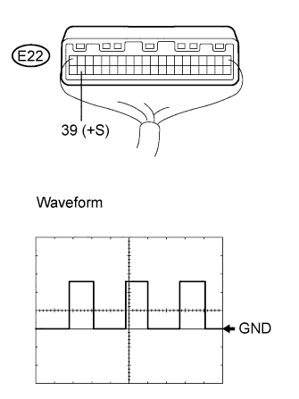
Check the output signal waveform.
Remove the combination meter, but do not disconnect the connector.
Connect an oscilloscope to terminal E22-39 and the body ground.
Start the engine.
Check the signal waveform according to the condition(s) in the table below.
| Item | Condition |
| Tool setting | 5 V/DIV, 20 ms/DIV |
| Vehicle condition | Driving at approx. 20 km/h (12.4 mph) |
| 3. CHECK TACHOMETER |
Check the operation.
Connect the tune-up test tachometer, and start the engine.
Compare the result of the test with the standard indication.
| Standard indication (rpm) | Acceptable range (rpm) Data in ( ) are for reference |
| 700 | 630 to 770 |
| 1,000 | (900 to 1,100) |
| 2,000 | (1,850 to 2,150) |
| 3,000 | 2,800 to 3,200 |
| 4,000 | (3,800 to 4,200) |
| 5,000 | 4,800 to 5,200 |
| 6,000 | (5,750 to 6,250) |
| 7,000 | 6,700 to 7,300 |
| 8,000 | (7,700 to 8,300) |
| 4. CHECK FUEL RECEIVER GAUGE |
![]() |
Disconnect the connector from the sender gauge.
Turn the ignition switch on (IG), then check the position of the receiver gauge needle.
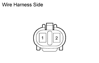
Connect terminals 1 and 2 on the wire harness side connector of the fuel sender gauge.
Turn the ignition switch on (IG), then check the position of the receiver gauge needle.
| 5. CHECK FUEL LEVEL WARNING LIGHT |
Disconnect the connector from the sender gauge.
Turn the ignition switch on (IG), check that the fuel level needle indicates EMPTY and fuel level warning light comes on.
| 6. CHECK BRAKE WARNING LIGHT |
Inspect the parking brake warning light.
Disconnect the connector from the parking brake switch.
Turn the ignition switch on (IG).
Ground the terminal of the wire harness side connector, and then check that the parking brake warning light illuminates.
| 7. CHECK OIL PRESSURE WARNING LIGHT (except Europe) |
Disconnect the connector from the engine oil pressure switch.
Turn the ignition switch on (IG).
Ground the terminal of the wire harness side connector, then check the engine oil pressure warning light.