MANUAL TRANSAXLE UNIT > REASSEMBLY |
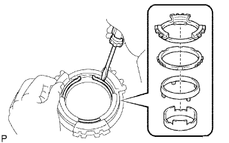
| 1. INSTALL SYNCHRONIZER PULL RING |
|
Install the No. 5 synchronizer ring middle, No. 5 synchronizer ring outer and synchronizer pull ring to the No. 5 synchronizer ring inner. Using a screwdriver, fix them in place with the synchronizer pull ring snap ring.
| 2. INSTALL NO. 5 SYNCHRONIZER RING MIDDLE |
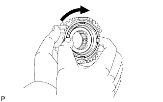 |
Check that the No. 5 synchronizer ring middle rotates smoothly.
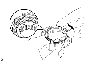 |
Check that the No. 5 synchronizer ring middle does not rotate while being pushed against the No. 3 clutch hub.
| 3. INSTALL NO. 3 SYNCHROMESH SHIFTING KEY SPRING |
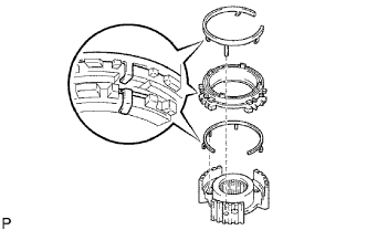 |
Install the No. 3 synchromesh shifting key spring to the No. 3 transaxle clutch hub.
Install the synchronizer ring set and No. 3 synchromesh shifting key spring to the No. 3 transaxle clutch hub.
| 4. INSTALL FRONT TRANSAXLE CASE COVER OIL SEAL |
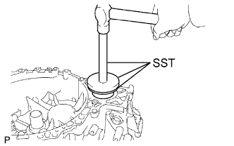 |
Using SST and a hammer, tap in a new front transaxle case cover oil seal.
Coat the lip of the oil seal with MP grease.
| 5. INSTALL FRONT DIFFERENTIAL CASE FRONT TAPERED ROLLER BEARING |
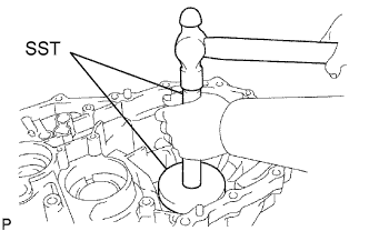 |
Using SST and a hammer, tap in the front tapered roller bearing (outer race) to the front differential case.
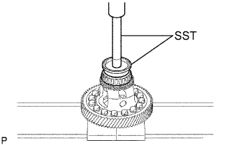 |
Using SST and a press, press in the front tapered roller bearing (inner race) to the front differential case.
| 6. INSTALL FRONT DIFFERENTIAL CASE REAR TAPERED ROLLER BEARING |
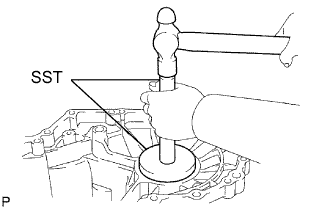 |
Install the rear shim.
Using SST and a hammer, tap in the rear tapered roller bearing (outer race).
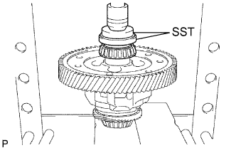 |
Using SST and a press, press in the rear tapered roller bearing (inner race).
| 7. INSTALL TRANSAXLE CASE OIL SEAL |
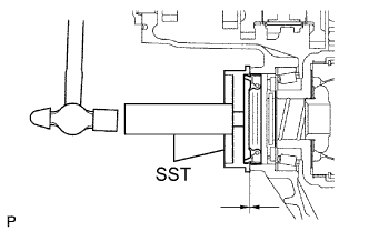 |
Using SST and a hammer, tap in a new oil seal to the transaxle case.
Coat the oil seal lip with MP grease.
| 8. INSTALL REAR OUTPUT SHAFT BEARING |
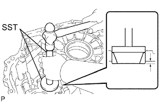 |
Using SST and a hammer, tap in the rear bearing (outer race) to the transaxle case.
| 9. INSTALL OUTPUT SHAFT COVER |
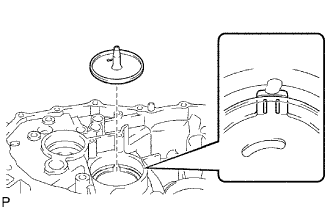 |
Coat the shaft cover with MP grease, and install it to the transaxle case.
| 10. INSTALL FRONT OUTPUT SHAFT BEARING |
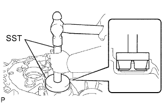 |
Using SST and a hammer, tap in the front bearing (outer race).
| 11. ADJUST OUTPUT SHAFT BEARING PRELOAD |
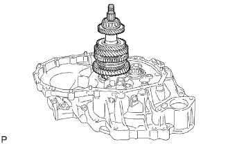 |
Install the output shaft to the transaxle case.
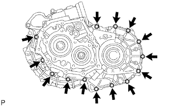 |
Install the transaxle case to the transaxle case with the 14 bolts.
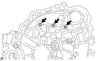 |
Install the 3 bolts on the transaxle side.
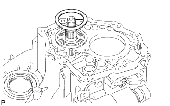 |
Install the output shaft rear bearing shim to the output shaft.
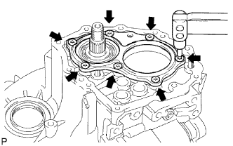 |
Using a T45 "torx" socket, install the rear bearing retainer to the transaxle case with the 7 "torx" screws.
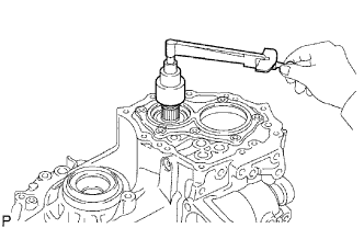 |
Turn the output shaft in both directions and check that it turns smoothly.
Temporarily install the output shaft rear set nut.
Using a socket wrench and torque wrench, inspect the preload.
| Bearing | Specified Condition |
| New | 0.8 to 1.6 N*m (8.16 to 16.32 kgf*cm, 7.1 to 14.2 in.lbf) |
| Used | 0.5 to 1.0 N*m (5.10 to 10.20 kgf*cm, 4.4 to 8.9 in.lbf) |
If preload is out of the specification, select a proper output shaft rear bearing shim and adjust the preload.
| Part No | Mark | Thickness |
| 90564-59001 | 0 | 1.30 mm (0.0512 in.) |
| 90564-59002 | 1 | 1.35 mm (0.0531 in.) |
| 90564-59003 | 2 | 1.40 mm (0.0551 in.) |
| 90564-59004 | 3 | 1.45 mm (0.0571 in.) |
| 90564-59005 | 4 | 1.50 mm (0.0591 in.) |
| 90564-59006 | 5 | 1.55 mm (0.0610 in.) |
| 90564-59007 | 6 | 1.60 mm (0.0630 in.) |
| 90564-59008 | 7 | 1.65 mm (0.0650 in.) |
| 90564-59009 | 8 | 1.70 mm (0.0669 in.) |
| 90564-59010 | 9 | 1.75 mm (0.0689 in.) |
| 90564-59011 | A | 1.80 mm (0.0669 in.) |
| 90564-59012 | B | 1.85 mm (0.0728 in.) |
| 90564-59013 | C | 1.90 mm (0.0748 in.) |
| 90564-59014 | D | 1.95 mm (0.0768 in.) |
| 90564-59015 | E | 2.00 mm (0.787 in.) |
| 90564-59016 | F | 2.05 mm (0.0807 in.) |
| 90564-59017 | G | 2.10 mm (0.0827 in.) |
| 90564-59018 | H | 2.15 mm (0.0846 in.) |
| 90564-59019 | J | 2.20 mm (0.0866 in. ) |
| 90564-59020 | K | 2.25 mm (0.0886 in.) |
| 90564-59021 | L | 2.30 mm (0.0906 in.) |
| 90564-59022 | M | 2.35 mm (0.0925 in.) |
| 90564-59023 | N | 2.40 mm (0.0945 in.) |
| 90564-59024 | P | 2.45 mm (0.0965 in.) |
| 90564-59025 | Q | 2.50 mm (0.0984 in.) |
Remove the output shaft rear set nut from the output shaft.
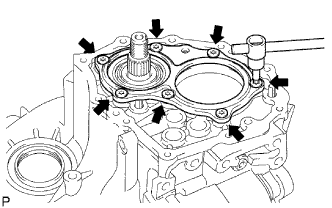 |
Using a T45 "torx" socket, remove the 7 "torx" screws and rear bearing retainer from the manual transaxle case.
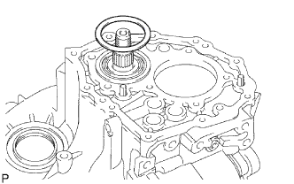 |
Remove the output shaft rear bearing shim from the output shaft.
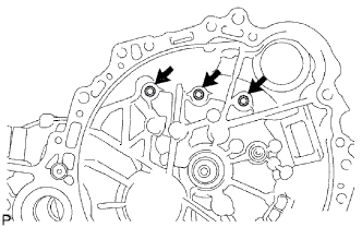 |
Remove the 3 bolts.
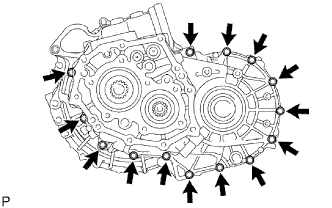 |
Remove the 14 bolts and transaxle case from the transaxle case.
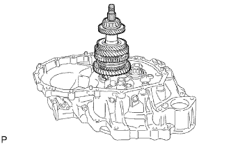 |
Remove the output shaft assembly from the front transaxle case.
| 12. ADJUST TAPERED ROLLER BEARING PRELOAD |
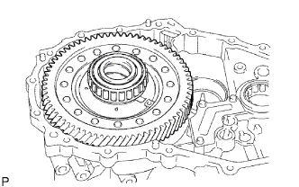 |
Install the bearing to the transaxle case.
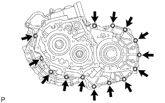 |
Install the 14 bolts and transaxle case to the transaxle case.
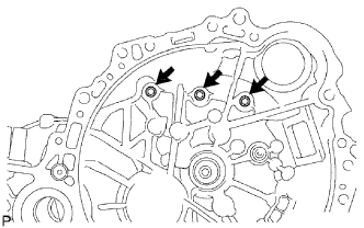 |
Install the 3 bolts on the front transaxle case side.
Turn the differential case in both directions and check that it turns smoothly.
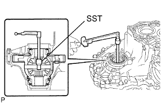 |
Using SST and a torque wrench, measure the preload.
| Bearing | Specified Condition |
| New | 0.8 to 1.6 N*m (8.16 to 16.32 kgf*cm, 7.1 to 14.2 in.*lbf) |
| Used | 0.5 to 1.0 N*m (5.10 to 10.2 kgf*cm, 4.4 to 8.9 in.*lbf) |
| Part No. | Mark | Thickness |
| 90564-56055 | 0 | 2.00 mm (0.0787 in.) |
| 90564-56056 | 1 | 2.05 mm (0.0807 in.) |
| 90564-56057 | 2 | 2.10 mm (0.0827 in.) |
| 90564-56058 | 3 | 2.15 mm (0.0846 in.) |
| 90564-56059 | 4 | 2.20 mm (0.0866 in.) |
| 90564-56060 | 5 | 2.25 mm (0.0886 in.) |
| 90564-56061 | 6 | 2.30 mm (0.0906 in.) |
| 90564-56062 | 7 | 2.35 mm (0.0925 in.) |
| 90564-56063 | 8 | 2.40 mm (0.0945 in.) |
| 90564-56064 | 9 | 2.45 mm (0.0965 in.) |
| 90564-56065 | A | 2.50 mm (0.0984 in.) |
| 90564-56066 | B | 2.55 mm (0.1004 in.) |
| 90564-56067 | C | 2.60 mm (0.1024 in.) |
| 90564-56068 | D | 2.65 mm (0.1043 in.) |
| 90564-56069 | E | 2.70 mm (0.1063 in.) |
| 90564-56070 | F | 2.75 mm (0.1083 in.) |
| 90564-56071 | G | 2.80 mm (0.1102 in.) |
| 90564-56072 | H | 2.85 mm (0.1122 in.) |
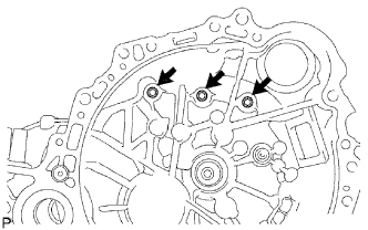 |
Remove the 3 bolts.
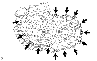 |
Remove the 14 bolts and transaxle case from the transaxle case.
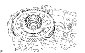 |
Remove the bearing from the transaxle case.
| 13. INSTALL FRONT TRANSAXLE CASE OIL SEAL |
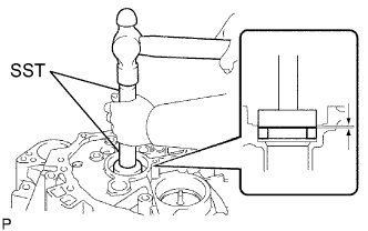 |
Using SST and a hammer, tap in a new oil seal to the transaxle case.
Coat the lip of the oil seal with MP grease.
| 14. INSTALL FRONT INPUT SHAFT BEARING |
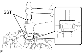 |
Coat the input shaft front bearing with gear oil, and using SST, tap in it to the transaxle case.
| 15. INSTALL MANUAL TRANSAXLE CASE RECEIVER |
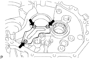 |
Install the receiver to the transaxle case with the 3 bolts.
| 16. INSTALL DIFFERENTIAL CASE ASSEMBLY |
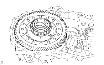 |
Coat the differential case tapered roller bearing with gear oil, and install the differential case to the transaxle case.
| 17. INSTALL OUTPUT SHAFT ASSEMBLY |
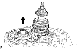 |
Apply gear oil to each sliding part of the output shaft.
Slightly lift up on the differential case at an angle, and install the output shaft to the transaxle case.
| 18. INSTALL INPUT SHAFT ASSEMBLY |
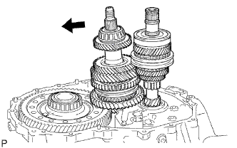 |
Apply gear oil to each sliding part of the input shaft.
Install the input shaft to the transaxle case while tilting the output shaft.
| 19. INSTALL NO. 2 GEAR SHIFT FORK |
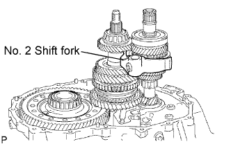 |
Coat the No. 2 gear shift fork with gear oil, and install it to the input shaft assembly.
| 20. INSTALL NO. 3 GEAR SHIFT FORK |
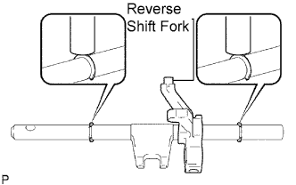 |
Install the reverse shift fork to the No. 3 gear shift fork shaft.
Using a brass bar and hammer, tap in the 2 shift fork shaft snap rings to the No. 3 gear shift fork shaft.
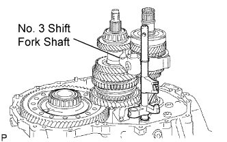 |
Apply gear oil to each sliding part of the No. 3 gear shift fork shaft, and install it to the transaxle case.
| 21. INSTALL NO. 1 GEAR SHIFT FORK |
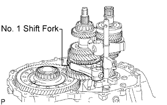 |
Apply gear oil to each sliding part of the No. 1 gear shift fork, and install it to the output shaft assembly.
| 22. INSTALL NO. 2 GEAR SHIFT FORK |
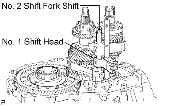 |
Apply gear oil to each sliding part of the No. 2 gear shift fork shaft and No. 1 gear shift head, and install them to the transaxle case.
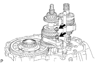 |
Install the shift fork set bolt and shift head set bolt to the No. 1 gear shift head and No. 2 gear shift fork.
| 23. INSTALL REVERSE SHIFT FORK ROLLER |
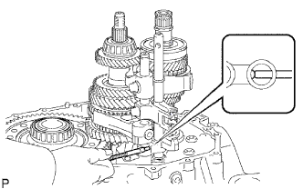 |
Using a magnetic finger, install the reverse shift fork roller to the reverse shift fork.
| 24. INSTALL NO. 1 GEAR SHIFT FORK SHAFT |
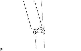 |
Using a brass bar and hammer, tap in the shaft snap ring to the No. 1 shift fork shaft.
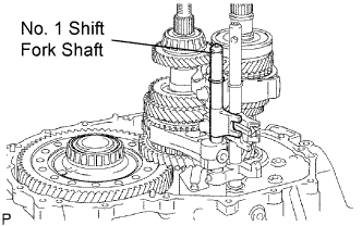 |
Install the No. 1 gear shift fork shaft to the transaxle case.
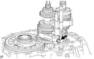 |
Install the shift fork set bolt to the No. 1 gear shift fork.
| 25. INSTALL REVERSE SHIFT ARM BRACKET ASSEMBLY |
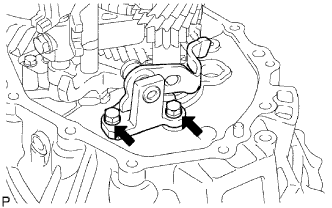 |
Install the reverse shift arm bracket to the transaxle case with the 2 bolts.
| 26. INSTALL REVERSE IDLER GEAR SUB-ASSEMBLY |
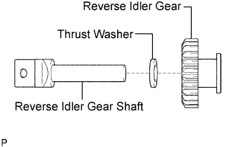 |
Coat the reverse idler gear and thrust washer with gear oil, and install them to the reverse idler gear shaft.
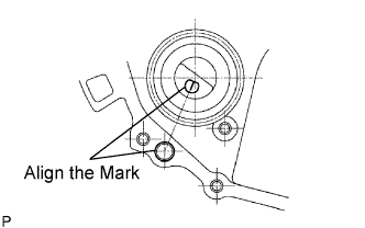 |
Install the reverse idler gear with the reverse idler gear shaft to the transaxle case.
| 27. INSTALL TRANSAXLE MAGNET |
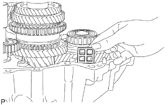 |
Clean the transaxle magnet, and install it to the transaxle case.
| 28. INSTALL REVERSE RESTRICT PIN ASSEMBLY |
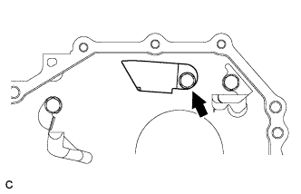 |
Install the transmission oil baffle and reverse restrict pin with the bolt.
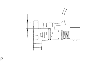 |
Install the reverse restrict pin to the transaxle case.
Using a 5 mm pin punch and hammer, tap in the slotted spring pin.
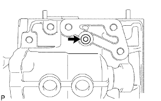 |
Coat the reverse restrict pin plug with adhesive. Using a 6 mm hexagon wrench, install the plug to the manual transaxle case.
| 29. INSTALL NO. 1 OIL RECEIVER PIPE |
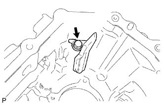 |
Install the oil receiver pipe to the transaxle case with the bolt.
| 30. INSTALL NO. 2 OIL RECEIVER PIPE |
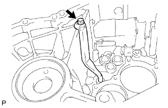 |
Install the oil receiver pipe to the transaxle case with the bolt.
| 31. INSTALL MANUAL TRANSAXLE CASE |
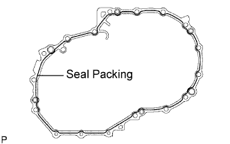 |
Apply seal packing to the transaxle case in a continuous line, as shown in the illustration.
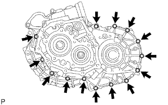 |
Install the transaxle case to the transaxle case with the 14 bolts.
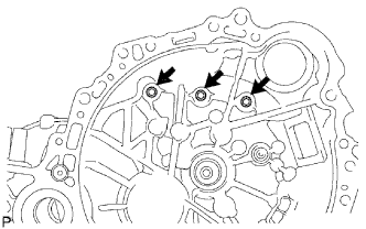 |
Coat the 3 bolts with adhesive, and install them on the transaxle case side.
| 32. INSTALL CLUTCH TUBE BRACKET |
Install the clutch tube bracket with the bolt.
| 33. INSTALL REVERSE IDLER GEAR SHAFT BOLT |
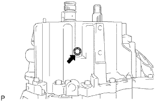 |
Coat the reverse idler gear shaft bolt with adhesive, and install a new reverse idler gear shaft gasket and the reverse idler gear shaft bolt to the transaxle case.
| 34. INSTALL SHIFT FORK SHAFT SHAFT SNAP RING |
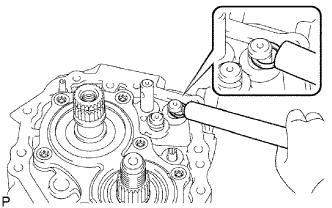 |
Using a brass bar and hammer, tap in the shaft snap ring to the No. 1 gear shift fork shaft.
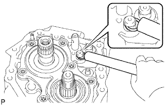 |
Using a brass bar and hammer, tap in the shaft snap ring to the No. 2 gear shift fork shaft.
| 35. INSTALL INPUT SHAFT REAR BEARING SHAFT SNAP RING |
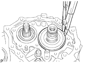 |
Using a snap ring expander, install the shaft snap ring.
| 36. INSTALL OUTPUT SHAFT REAR BEARING SHIM |
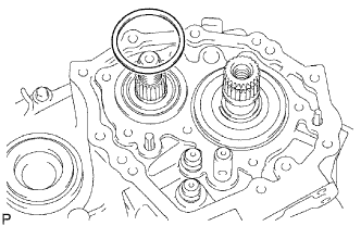 |
Install the output shaft rear bearing shim to the output shaft.
| 37. INSTALL REAR BEARING RETAINER |
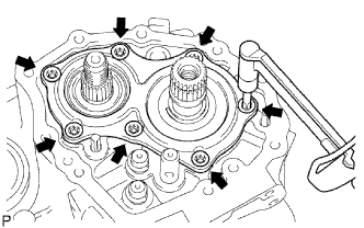 |
Coat the 7 bolts with adhesive. Using a T45 "torx" socket, install the bearing retainer with the bolts.
| 38. INSTALL 5TH DRIVEN GEAR |
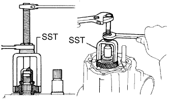 |
Using SST, install the 5th driven gear to the output shaft.
| 39. INSTALL 5TH GEAR NEEDLE ROLLER BEARING |
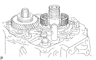 |
Coat the needle roller bearing with gear oil, and install it to the input shaft.
| 40. INSTALL 5TH GEAR |
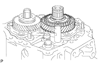 |
Coat the 5th gear with gear oil, and install it to the input shaft.
| 41. INSTALL NO. 3 TRANSAXLE CLUTCH HUB |
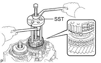 |
Using SST, install the No. 3 transaxle clutch hub to the input shaft.
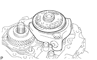 |
Install the No. 3 transaxle hub sleeve and No. 3 gear shift fork to the No. 3 transaxle clutch hub.
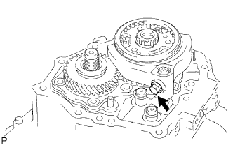 |
Coat the shift fork set bolt with adhesive, and install it to the No. 3 gear shift fork.
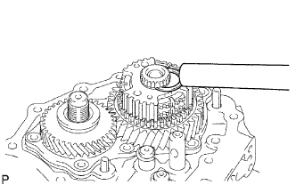 |
Select an appropriate No. 3 transaxle clutch hub shaft snap ring that allows the minimum amount of axial play. Using a brass bar and hammer, tap in the No. 3 transaxle clutch hub shaft snap ring.
| Part No. | Mark | Thickness |
| 90520-27061 | a | 1.75 to 1.80 mm (0.0689 to 0.0709 in.) |
| 90520-27062 | b | 1.80 to 1.85 mm (0.0709 to 0.0728 in.) |
| 90520-27063 | c | 1.85 to 1.90 mm (0.0728 to 0.0748 in.) |
| 90520-27064 | d | 1.90 to 1.95 mm (0.0748 to 0.0768 in.) |
| 90520-27065 | e | 1.95 to 2.00 mm (0.0768 to 0.0787 in.) |
| 90520-27066 | f | 2.00 to 2.05 mm (0.0787 to 0.0807 in.) |
| 90520-27067 | g | 2.05 to 2.10 mm (0.0807 to 0.0827 in.) |
| 90520-27068 | h | 2.10 to 2.15 mm (0.0827 to 0.0846 in.) |
| 90520-27069 | j | 2.15 to 2.20 mm (0.0846 to 0.0866 in.) |
| 42. INSPECT 5TH GEAR RADIAL CLEARANCE |
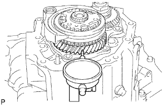 |
Using a dial indicator, measure the 5th gear radial clearance.
| 43. INSPECT 5TH GEAR THRUST CLEARANCE |
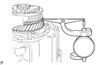 |
Using a dial indicator, measure the 5th gear thrust clearance.
| 44. INSTALL TRANSAXLE OUTPUT SHAFT REAR SET NUT |
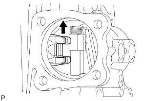 |
Engage the 2 gears simultaneously to lock the transaxle.
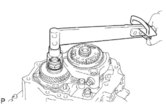 |
Install a new transaxle output shaft rear set nut.
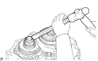 |
Using a chisel and hammer, stake the rear set nut.
Disengage the 2 gears.
| 45. INSTALL MANUAL TRANSAXLE CASE COVER SUB-ASSEMBLY |
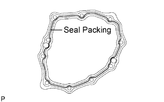 |
Apply seal packing to the transaxle case cover, as shown in the illustration.
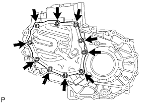 |
Install the transaxle case cover to the transaxle case with the 10 bolts.
| 46. INSTALL DRAIN PLUG SUB-ASSEMBLY |
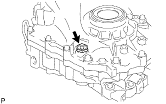 |
Install a new gasket and the drain plug to the transaxle case.
| 47. INSTALL MANUAL TRANSAXLE FILLER PLUG |
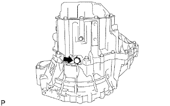 |
Install a new gasket and the filler plug to the transaxle case.
| 48. INSTALL SHIFT AND SELECT LEVER SHAFT ASSEMBLY |
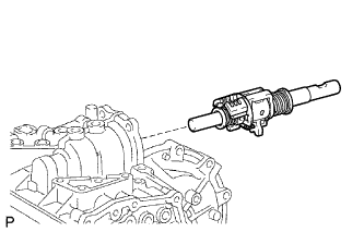 |
Coat the shift and select lever shaft with gear oil, and install it to the transaxle case.
| 49. INSTALL CONTROL SHAFT COVER |
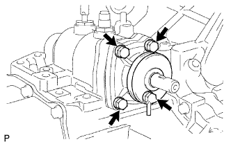 |
Coat the 4 bolts with adhesive, and install a new gasket and the control shaft cover with the 4 bolts.
| 50. INSTALL BACK-UP LIGHT SWITCH ASSEMBLY |
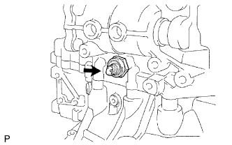 |
Install a new gasket and the back-up light switch to the manual transaxle case.
| 51. INSTALL MANUAL TRANSAXLE BREATHER PLUG |
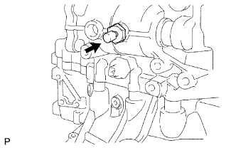 |
Install a new gasket and the breather plug to the case.
| 52. INSTALL NO. 1 LOCK BALL ASSEMBLY |
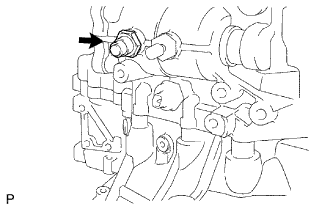 |
Install the No. 1 lock ball to the transaxle case.
| 53. INSTALL CONTROL SHIFT LEVER |
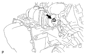 |
Install the control shift lever with the shift outer lever lock pin to the shift and select lever shaft.
Install the spring washer with the nut.
| 54. INSTALL SELECTING BELLCRANK ASSEMBLY |
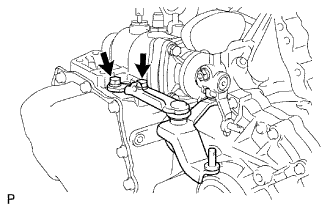 |
Install the shift and select lever bush to the selecting bellcrank.
Coat the 2 bolts with adhesive, and install the selecting bellcrank to the transaxle case with the bolts.
| 55. INSTALL SPEEDOMETER DRIVEN HOLE COVER SUB-ASSEMBLY |
Install a new O-ring to the hole cover.
Install the hole cover to the transaxle case with the bolt.
| 56. INSTALL CLUTCH RELEASE FORK BOOT |
Install the clutch release fork boot to the transaxle case.
| 57. INSTALL RELEASE FORK SUPPORT |
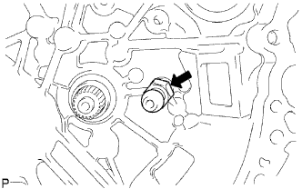 |
Using a deep socket wrench, install the release fork support to the transaxle case.
| 58. INSTALL CLUTCH RELEASE BEARING ASSEMBLY |
Coat the clutch release bearing with Multemp 8158 Grease or equivalent, and install it to the clutch release fork with the clutch release bearing clip.
| 59. INSTALL CLUTCH RELEASE FORK SUB-ASSEMBLY |
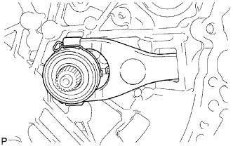 |
Apply clutch spline grease to the input shaft spline.
Install the clutch release fork to the input shaft.