SHIFT AND SELECT LEVER SHAFT > REASSEMBLY |
| 1. INSTALL CONTROL SHAFT COVER OIL SEAL |
|
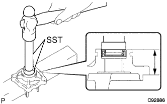
Using SST and a hammer, tap in a new control shaft cover oil seal to the control shaft cover.
| 2. INSTALL SHIFT AND SELECT LEVER SHAFT DUST BOOT |
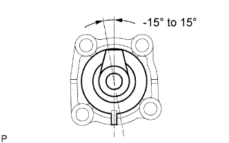 |
Install the shift and select lever shaft dust boot to the control shaft cover.
| 3. INSTALL NO. 1 SELECT SPRING SEAT SHAFT SNAP RING |
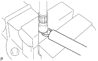 |
Using a brass bar and hammer, tap in the shaft snap ring.
| 4. REMOVE NO. 1 SHIFT LEVER INNER |
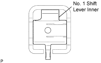 |
Coat the No. 1 shift lever inner and shift inter lock plate with MP grease, and install them.
| 5. INSTALL SHIFT INTER LOCK PLATE COVER |
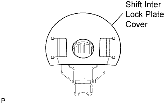 |
Install the shift inter lock plate cover to the shift inter lock plate.
| 6. INSTALL NO. 1 SELECT SPRING SEAT |
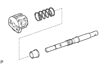 |
Coat the No. 1 select spring seat with MP grease, and install it.
Install the No. 1 select return compression spring and shift inter lock plate assembly to the shift and select lever shaft.
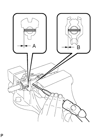 |
Hold the shift and select lever shaft in a vise with soft jaws.
Using a 5 mm pin punch and a hammer, install the 2 shift lever inner slotted pins to the shift and select lever shaft.
| 7. INSTALL NO. 2 SHIFT LEVER INNER |
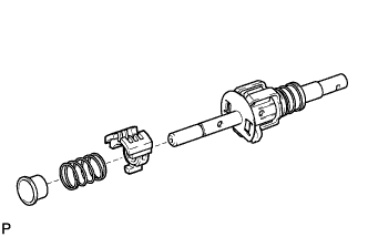 |
Install the No. 2 shift lever inner and No. 2 select return compression spring to the shift and select lever shaft.
Coat the select spring seat No. 2 with MP grease, and install it to the shift and select lever shaft.
Using a brass bar and hammer, tap in the No. 2 select spring seat shaft snap ring to the shift and select lever shaft.
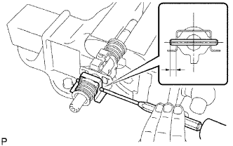 |
Install the transaxle oil baffle. Using a 5 mm pin punch and hammer, tap in the No. 2 shift lever inner slotted pin to the shift and select lever shaft.
| 8. INSTALL NO. 2 SELECTING BELLCRANK BUSH |
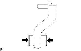 |
Coat the bushes with MP grease, and install them to the No. 2 selecting bellcrank.
| 9. INSTALL NO. 2 SELECTING BELLCRANK DUST COVER |
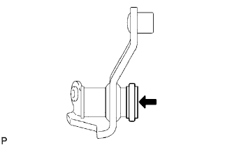 |
Coat the dust cover with MP grease, and install it to the No. 2 selecting bellcrank.
| 10. INSTALL SELECTING BELLCRANK SUPPORT SUB-ASSEMBLY |
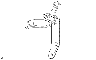 |
Install the selecting bellcrank support to the No. 2 selecting bellcrank.
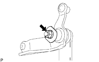 |
Install the No. 2 selecting bellcrank plate washer, wave washer and nut.
| 11. INSTALL NO. 1 SELECTING BELLCRANK DUST COVER |
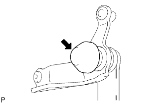 |
Install the dust cover to the No. 2 selecting bellcrank.
| 12. INSTALL SHIFT AND SELECT LEVER BUSH |
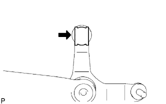 |
Install the bush to the No. 2 selecting bellcrank.