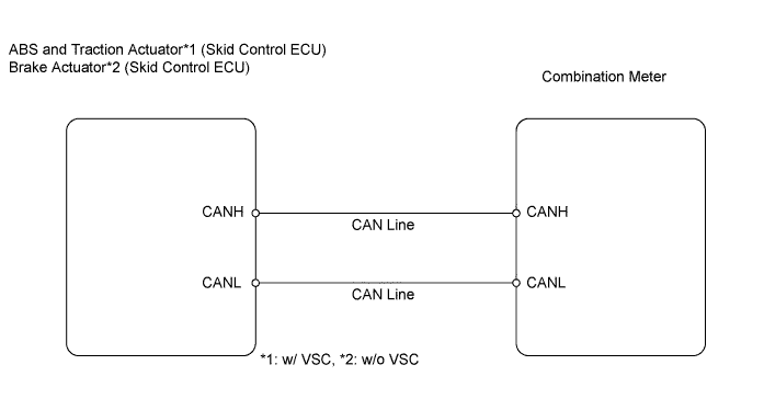
METER / GAUGE SYSTEM > Speedometer Malfunction |
| 1.PERFORM ACTIVE TEST USING INTELLIGENT TESTER (Speed Meter Operation) |
Connect the intelligent tester to the DLC3.
Turn the ignition switch on (IG) and turn the tester ON.
Perform the ACTIVE TEST according to the prompts displayed on the tester.
| Tester Display | Test Part | Control Range |
| Speed Meter Operation | 0 / 40 / 80 / 120 / 160 / 200 / 240 km | Value selected during Active Test is displayed |
|
| ||||
| OK | |
 |
| 2.READ VALUE USING DATA LIST (Vehicle Speed Meter) |
Connect the intelligent tester to the DLC3.
Turn the ignition switch on (IG) and the tester ON.
Read the Data List according to the prompts displayed on the tester.
| Tester Display | Measurement Item/Range | Normal Condition | Diagnostic Note |
| Vehicle Speed Meter | Vehicle speed / Min.: 0 km/h (0 mph), Max.: 255 km/h (158 mph) | Almost same as actual vehicle speed (When driving) | - |
|
| ||||
| OK | ||
 | ||
| ||
