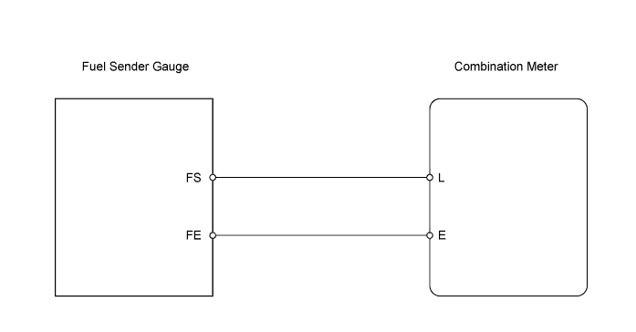
METER / GAUGE SYSTEM > Fuel Receiver Gauge Malfunction |
| 1.PERFORM ACTIVE TEST USING INTELLIGENT TESTER (Fuel Meter Operation) |
Connect the intelligent tester to the DLC3.
Turn the ignition switch on (IG) and turn the tester ON.
Perform the ACTIVE TEST according to the prompts displayed on the tester.
| Tester Display | Test Part | Control Range |
| Fuel Meter Operation | EMPTY / 1/2 / FULL | Value selected during Active Test is displayed |
|
| ||||
| OK | |
 |
| 2.READ VALUE USING DATA LIST (Fuel Input (A/D)) |
Connect the intelligent tester to the DLC3.
Turn the ignition switch on (IG) and the tester ON.
Read the Data List according to the prompts displayed on the tester.
| Tester Display | Measurement Item/Range | Normal Condition | Diagnostic Note |
| Fuel Input (A/D) | Fuel input signal / Min.: 0, Max.: 255 | Fuel gauge indicates (F): 33 Fuel gauge indicates (3/4): 98 Fuel gauge indicates (1/2): 144 Fuel gauge indicates (1/4): 179 Fuel gauge indicates (E): 206 | - |
|
| ||||
| OK | |
|
| 3.INSPECT FUEL SENDER GAUGE ASSEMBLY |
Remove the fuel sender gauge.
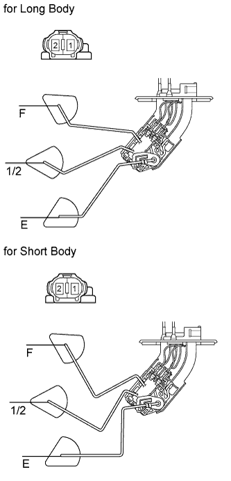 |
Measure the resistance of the gauge.
| Tester Connection | Float Level | Specified Condition |
| 1 - 2 | F | 15.0 +-1.5 Ω |
| 1 - 2 | 1/2 | 212.5 +-12.2 Ω |
| 1 - 2 | E | 410.0 +-4.5 Ω |
|
| ||||
| OK | |
|
| 4.CHECK WIRE HARNESS (COMBINATION METER - FUEL SENDER GAUGE) |
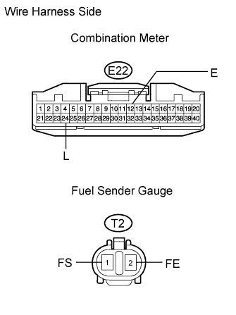 |
Disconnect the E22 meter connector.
Disconnect the T2 gauge connector.
Measure the resistance of the wire harness side connectors.
| Tester Connection | Specified Condition |
| E22-24 (L) - T2-1 (FS) | Below 1 Ω |
| E22-12 (E) - T2-2 (FE) | Below 1 Ω |
| E22-24 (L) or T2-1 (FS) - Body ground | 10 kΩ or higher |
| E22-12 (E) or T2-2 (FE) - Body ground | 10 kΩ or higher |
|
| ||||
| OK | ||
 | ||
| ||
