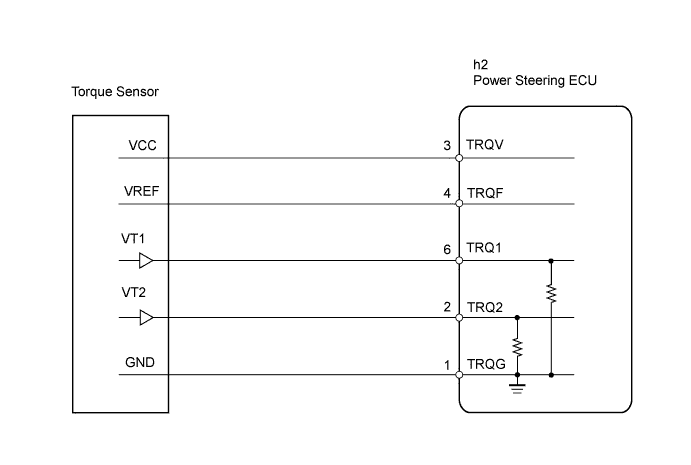
DTC C1511/11 Torque Sensor 1 Malfunction |
DTC C1512/11 Torque Sensor 2 Malfunction |
DTC C1513/11 Torque Sensor Deviation Excessive |
DTC C1514/11 Torque Sensor Power Supply Voltage Malfunction |
| DTC No. | DTC Detection Condition | Trouble Area |
| C1511/11 | Torque sensor malfunction |
|
| C1512/11 | ||
| C1513/11 | ||
| C1514/11 |
| 1.CHECK CONNECTOR CONNECTION CONDITION (TORQUE SENSOR - POWER STEERING ECU) |
Check the installation condition of the torque sensor connector.
|
| ||||
| OK | |
 |
| 2.CHECK POWER STEERING ECU |
Turn the ignition switch on (IG).
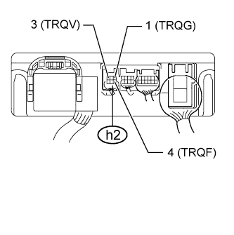 |
Measure the voltage of the ECU.
| Tester Connection | Condition | Specified Condition |
| h2-4 (TRQF) - h2-1 (TRQG) | Always | 3.35 to 3.37 V |
| h2-3 (TRQV) - h2-1 (TRQG) | Always | 8.5 to 10.5 V |
|
| ||||
| OK | |
|
| 3.INSPECT TORQUE SENSOR |
Turn the ignition switch on (IG).
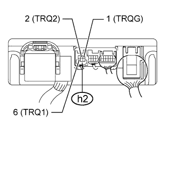 |
Measure the voltage of the ECU.
| Tester Connection | Condition | Specified Condition |
| h2-6 (TRQ1) - h2-1 (TRQG) | Steering wheel not turned (without load) | 2.3 to 2.7 V |
| Steering wheel turned to right with vehicle stopped | 2.5 to 4.04 V | |
| Steering wheel turned to left with vehicle stopped | 0.95 to 2.5 V | |
| h2-2 (TRQ2) - h2-1 (TRQG) | Steering wheel not turned (without load) | 2.3 to 2.7 V |
| Steering wheel turned to right with vehicle stopped | 0.95 to 2.5 V | |
| Steering wheel turned to left with vehicle stopped | 2.5 to 4.04 V |
Add the voltage measured at terminal TRQ1 minus 2.5 V to the voltage measured at terminal TRQ2 minus 2.5 V.
|
| ||||
| OK | ||
 | ||
| ||
