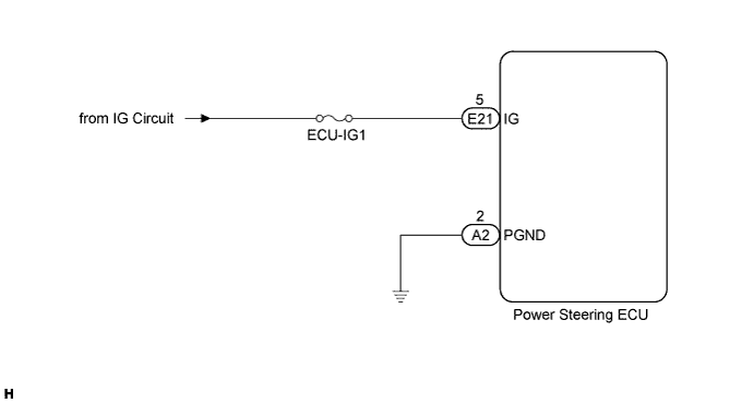
DTC C1551/25 IG Power Supply Voltage Malfunction |
| DTC No. | DTC Detection Condition | Trouble Area |
| C1551/25 | IG power source circuit malfunction inside ECU |
|
| 1.READ VALUE USING INTELLIGENT TESTER (IG POWER SUPPLY) |
Connect the intelligent tester to the DLC3.
Turn the ignition switch on (IG) and press the intelligent tester main switch ON.
Select the item "IG Power Supply" in the Data List and read the value displayed on the intelligent tester.
| Tester Display | Measurement Item/Range | Normal Condition | Specified Condition |
| IG Power Supply | ECU power source voltage: Min.: 0 V Max.: 20.1531 V | Ignition switch on (IG) | 10 to 14 V |
|
| ||||
| NG | |
 |
| 2.INSPECT FUSE (ECU-IG1) |
Remove the ECU-IG1 fuse from the instrument panel junction block.
Measure the resistance of the fuse.
|
| ||||
| OK | |
|
| 3.CHECK WIRE HARNESS (BATTERY - POWER STEERING ECU) |
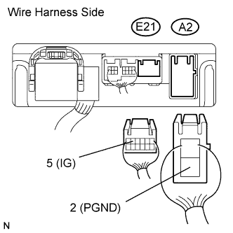 |
Disconnect the E21 and A2 ECU connectors.
Measure the voltage of the wire harness side connectors.
| Tester Connection | Condition | Specified Condition |
| E21-5 (IG) - A2-2 (PGND) | Ignition switch on (IG) | 10 to 14 V |
|
| ||||
| OK | ||
 | ||
| ||
