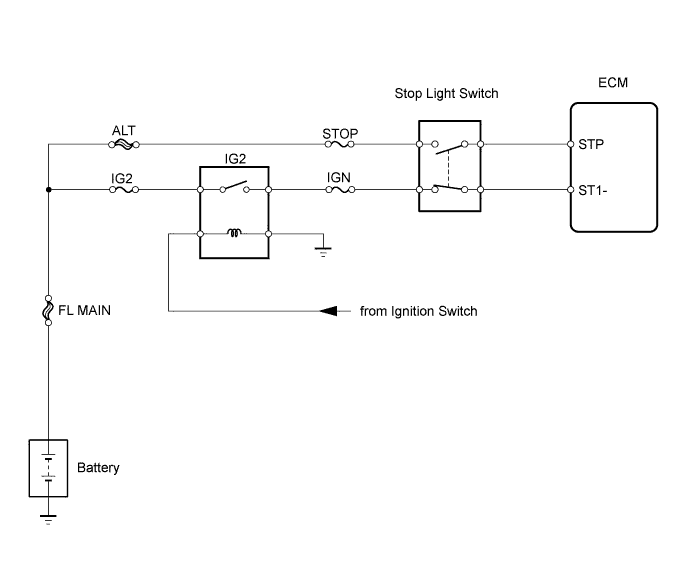
DTC P0571/52 Stop Light Switch Circuit |
| DTC Code | DTC Detection Condition | Trouble Area |
| P0571/52 | ECM detects malfunction of stop light switch circuit under both of following conditions:
|
|
| 1.INSPECT FUSE (STOP, IGN, IG2) |
Remove the STOP and IGN fuses from the instrument panel junction block.
Remove the IG2 fuse from the engine room No. 1 relay block.
Measure the resistance of the fuses.
|
| ||||
| OK | |
 |
| 2.INSPECT IG2 RELAY |
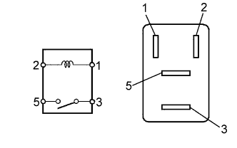 |
Remove the IG2 relay from the instrument panel junction block.
Measure the resistance of the relay.
| Tester Connection | Specified Condition |
| 3 - 5 | 10 kΩ or higher |
| Below 1 Ω (when battery voltage is applied to terminals 1 and 2) |
|
| ||||
| OK | |
|
| 3.INSPECT STOP LIGHT SWITCH |
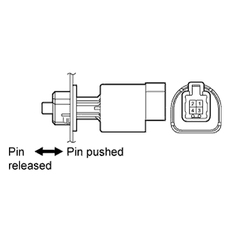 |
Remove the stop light switch.
Measure the resistance of the switch.
| Tester Connection | Switch Condition | Specified Condition |
| 1 - 2 | Not pushed | Below 1 Ω |
| 3 - 4 | Pushed | |
| 1 - 2 | Pushed | 10 kΩ or higher |
| 3 - 4 | Not pushed |
|
| ||||
| OK | |
|
| 4.CHECK WIRE HARNESS (SWITCH - BATTERY) |
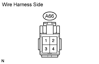 |
Disconnect the A66 switch connector.
Measure the voltage of the wire harness side connector.
| Tester Connection | Switch Condition | Specified Condition |
| A66-2 - Body ground | Always | 11 to 14 V |
| A66-4 - Body ground | Ignition switch ON |
|
| ||||
| OK | |
|
| 5.CHECK WIRE HARNESS (ECM - BATTERY) |
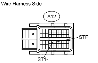 |
Disconnect the A12 ECM connector.
Turn the ignition switch ON.
Measure the voltage of the wire harness side connector.
| Tester Connection | Switch Condition | Specified Condition |
| A12-35 (ST1-) - Body ground | Depressed | 11 to 14 V |
| A12-36 (STP) - Body ground | Released | |
| A12-35 (ST1-) - Body ground | Released | Below 1 V |
| A12-36 (STP) - Body ground | Depressed |
|
| ||||
| OK | ||
 | ||
| ||
