 |
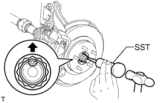
Using SST and a hammer, unstake the staked part of the nut.
- SST
- 09930-00010
- NOTICE:
- Loosen the staked part of the nut completely, otherwise the screw of the drive shaft may be damaged.
FRONT DRIVE SHAFT ASSEMBLY (for 2WD) > REMOVAL |
| 1. REMOVE FRONT WHEEL |
| 2. DRAIN AUTOMATIC TRANSAXLE FLUID |
Remove the drain plug and gasket, and drain ATF.
Install a new gasket and the drain plug.
| 3. DRAIN TRANSAXLE OIL |
for E352:
Drain the transaxle oil .
for EB61:
Drain the transaxle oil .
| 4. REMOVE FRONT AXLE HUB NUT |
|
Using SST and a hammer, unstake the staked part of the nut.
While applying the brakes, remove the lock axle hub nut.
| 5. REMOVE FRONT SPEED SENSOR LH |
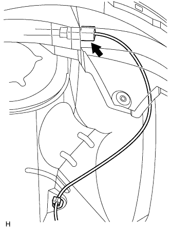 |
Disconnect the sensor connector.
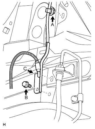 |
Remove the sensor clip (labeled A), bolt (labeled B) and sensor clamp (labeled C).
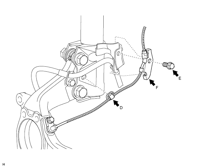
Remove the sensor clip (labeled D), bolt (labeled E) and sensor clamp (labeled F).
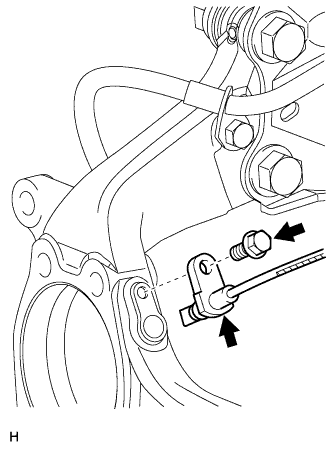 |
Remove the bolt and sensor from the knuckle.
| 6. REMOVE FRONT SPEED SENSOR RH |
| 7. DISCONNECT FRONT DISC BRAKE CYLINDER ASSEMBLY LH |
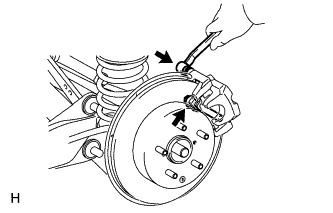 |
Remove the 2 bolts and cylinder.
| 8. DISCONNECT FRONT DISC BRAKE CYLINDER ASSEMBLY RH |
| 9. REMOVE FRONT STABILIZER LINK ASSEMBLY LH |
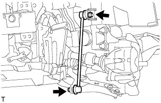 |
Remove the 2 nuts and stabilizer link.
| 10. REMOVE FRONT STABILIZER LINK ASSEMBLY RH |
| 11. DISCONNECT FRONT SUSPENSION LOWER NO. 1 ARM SUB-ASSEMBLY LH |
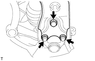 |
Remove the bolt and 2 nuts.
Disconnect the lower arm from the ball joint.
| 12. DISCONNECT FRONT SUSPENSION LOWER NO. 1 ARM SUB-ASSEMBLY RH |
| 13. DISCONNECT STEERING KNUCKLE WITH AXLE HUB LH |
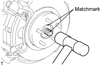 |
Put matchmarks on the drive shaft and axle hub.
Using a plastic-faced hammer, disconnect the steering knuckle with axle hub.
| 14. DISCONNECT STEERING KNUCKLE WITH AXLE HUB RH |
| 15. DISCONNECT TIE ROD END SUB-ASSEMBLY LH |
Remove the cotter pin and castle nut.
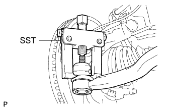 |
Using SST, disconnect the tie rod end from the steering knuckle.
| 16. DISCONNECT TIE ROD END SUB-ASSEMBLY RH |
| 17. REMOVE FRONT DRIVE SHAFT ASSEMBLY LH |
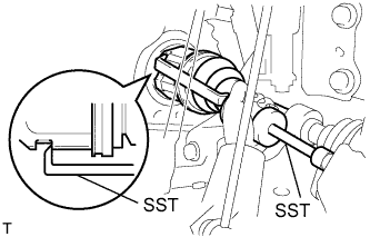 |
Using SST, remove the front drive shaft.
| 18. REMOVE FRONT DRIVE SHAFT ASSEMBLY RH |
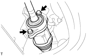 |
Remove the 2 bolts and pull out the drive shaft together with the drive shaft bearing case.
Remove the drive shaft from the transaxle.