FRONT DRIVE SHAFT ASSEMBLY (for 4WD) > DISASSEMBLY |
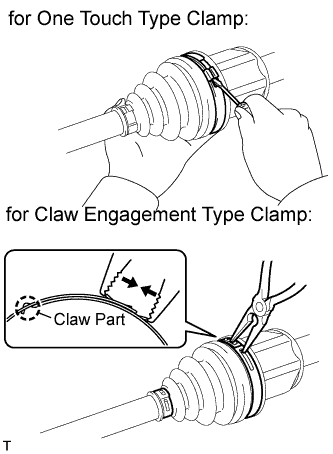
| 1. REMOVE FRONT AXLE INBOARD JOINT BOOT NO. 2 CLAMP LH |
|
for One Touch Type Clamp:
Using a screwdriver, remove the clamp, as shown in the illustration.
for Claw Engagement Type Clamp:
Using needle-nose pliers, remove the clamp, as shown in the illustration.
| 2. REMOVE FRONT AXLE INBOARD JOINT BOOT NO. 2 CLAMP RH |
| 3. REMOVE FRONT AXLE INBOARD JOINT BOOT CLAMP LH |
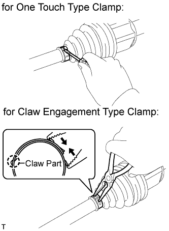 |
for One Touch Type Clamp:
Using a screwdriver, remove the inboard joint boot clamp, as shown in the illustration.
for Claw Engagement Type Clamp:
Using needle-nose pliers, remove the inboard joint boot clamp, as shown in the illustration.
| 4. REMOVE FRONT AXLE INBOARD JOINT BOOT CLAMP RH |
| 5. REMOVE FRONT AXLE INBOARD JOINT BOOT |
Remove the boot from the inboard joint.
| 6. REMOVE FRONT DRIVE INBOARD JOINT ASSEMBLY LH |
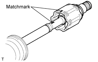 |
Remove any old grease from the inboard joint.
Put matchmarks on the inboard joint and outboard joint shaft.
Remove the inboard joint from the outboard joint shaft.
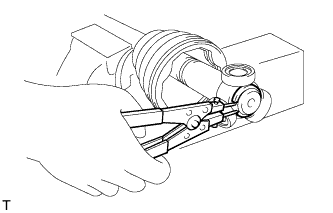 |
Using a snap ring expander, remove the shaft snap ring.
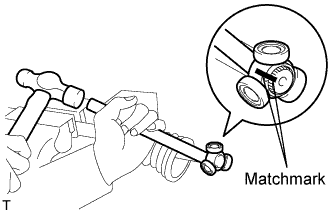 |
Put matchmarks on the outboard joint shaft and tripod.
Using a brass bar and hammer, tap off the tripod from the outboard joint shaft.
Remove the inboard joint boot.
| 7. REMOVE FRONT DRIVE INBOARD JOINT ASSEMBLY RH |
| 8. REMOVE FRONT DRIVE SHAFT DAMPER CLAMP (except E352F/E359F, EB61F) |
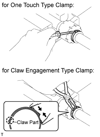 |
for One Touch Type Clamp:
Using a screwdriver, remove the drive shaft damper clamp, as shown in the illustration.
for Claw Engagement Type Clamp:
Using needle-nose pliers, remove the drive shaft damper clamp, as shown in the illustration.
| 9. REMOVE FRONT DRIVE SHAFT DAMPER (except E352F/E359F, EB61F) |
Remove the front drive shaft damper.
| 10. REMOVE FRONT DRIVE SHAFT DAMPER CLAMP RH |
| 11. REMOVE FRONT DRIVE SHAFT DAMPER RH |
| 12. REMOVE FRONT AXLE OUTBOARD JOINT BOOT NO. 2 CLAMP LH |
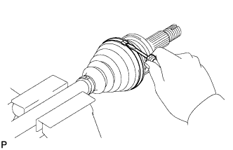 |
Using a screwdriver, remove the No. 2 outboard joint boot clamp, as shown in the illustration.
| 13. REMOVE FRONT AXLE OUTBOARD JOINT BOOT NO. 2 CLAMP RH |
| 14. REMOVE FRONT AXLE OUTBOARD JOINT BOOT CLAMP LH |
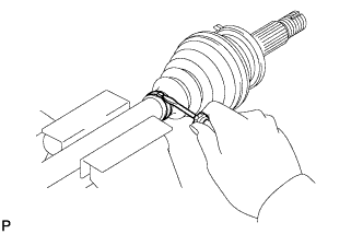 |
Using a screwdriver, remove the outboard joint boot clamp, as shown in the illustration.
| 15. REMOVE FRONT AXLE OUTBOARD JOINT BOOT CLAMP RH |
| 16. REMOVE FRONT AXLE OUTBOARD JOINT BOOT |
Remove the outboard joint boot from the outboard joint shaft.
Remove any old grease from the outboard joint.
| 17. REMOVE FRONT DRIVE SHAFT HOLE SNAP RING LH |
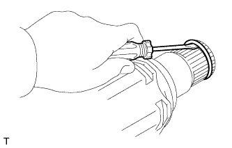 |
Using a screwdriver, remove the hole snap ring.
| 18. REMOVE FRONT DRIVE SHAFT DUST COVER LH |
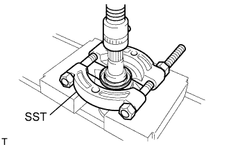 |
Using SST and a press, press out the inboard joint from the shaft dust cover to remove the shaft dust cover.
| 19. REMOVE FRONT DRIVE SHAFT DUST COVER RH |
Use the same procedures described for the LH side.
| 20. REMOVE FRONT DRIVE SHAFT BEARING |
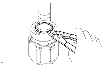 |
Using a snap ring expander, remove the snap ring.
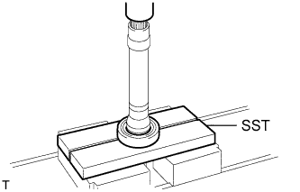 |
Using SST and a press, press out the inboard joint from the shaft bearing to remove the shaft bearing.
Remove the snap ring.