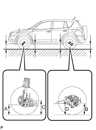
FRONT WHEEL ALIGNMENT > ADJUSTMENT |
| 1. INSPECT TIRES |
Inspect the tires (Click here).
| 2. MEASURE VEHICLE HEIGHT |
|
Press down on the vehicle several times to stabilize the suspension, and measure the vehicle height.
Measure the front vehicle height.
Measure the distance from the ground to the center of the lower suspension arm front mounting bolt.
Measure the rear vehicle height.
Measure the distance from the ground to the center of the body side No. 2 suspension arm mounting bolt.
| Item | Front C - A | Rear D - B |
| 215/70R16*1 | 89 mm (3.50 in.) | 59 mm (2.32 in.) |
| 225/65R17 235/55R18 | 97 mm (3.82 in.) | 67 mm (2.64 in.)*1 65 mm (2.56 in.)*2 |
| Australia | 87 mm (3.43 in.) | 55 mm (2.17 in.) |
| 3. INSPECT CAMBER, CASTER AND STEERING AXIS INCLINATION |
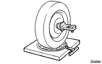 |
Install the camber-caster-kingpin gauge or place the front wheels on the center of the wheel alignment tester.
Inspect the camber, caster and steering axis inclination.
| Item | Camber Inclination |
| *215/70R16 | -0°08' +/-45' (-0.13° +/-0.75°) |
| 225/65R17 235/55R18 | -0°11' +/-45' (-0.18° +/-0.75°) |
| Australia | -0°07' +/-45' (-0.12° +/-0.75°) |
| Item | Caster Inclination |
| 215/70R16 *1 | 5°46' +/-45' (5.77° +/-0.75°) |
| 225/65R17 235/55R18 | 5°51' +/-45' (5.85° +/-0.75°) *1 5°50' +/-45' (5.83° +/-0.75°) *2 |
| Australia | 5°42' +/-45' (5.70° +/-0.75°) |
| Item | Steering Axis Inclination |
| *215/70R16 | 11°16' +/-45' (11.27° +/-0.75°) |
| 225/65R17 235/55R18 | 11°26' +/-45' (11.44° +/-0.75°) |
| Australia | 11°14' +/-45' (11.23° +/-0.75°) |
| 4. ADJUST CAMBER AND CASTER |
Remove the front wheel.
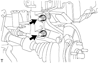 |
Remove the 2 nuts on the lower side of the shock absorber.
Clean the installation surfaces of the shock absorber and the steering knuckle.
Temporarily install the 2 nuts.
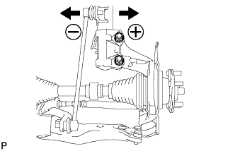 |
Fully push or pull the front axle hub in the direction of the required adjustment.
Tighten the 2 nuts.
Install the front wheel.
Check the camber.
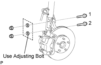
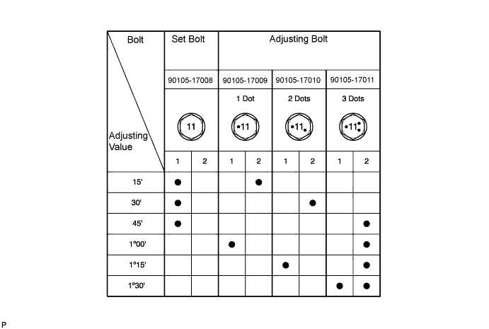
Repeat the steps mentioned above. When temporarily installing the 2 nuts, replace 1 or 2 selected bolts.
| 5. INSPECT TOE-IN |
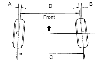 |
| Tire Size | Front A + B Rear C - D |
| *215/70R16 225/65R17 235/55R18 | A + B: 0°05' +/-10' (0.08° +/-0.16°) C - D: 1.0 +/-2.0 mm (0.04 +/-0.08 in.) |
| 6. ADJUST TOE-IN |
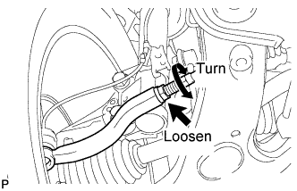 |
Remove the boot clips.
Loosen the tie rod end lock nuts.
Turn the right and left rack ends by an equal amount to adjust the toe-in to the center value.
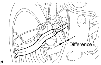 |
Make sure that the length of the right and left rack ends are approximately the same.
Tighten the tie rod end lock nuts.
Place the boots on the seats and install the clips.
| 7. INSPECT WHEEL ANGLE |
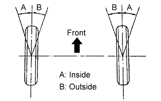 |
Turn the steering wheel to the left and right full lock positions, and measure the turning angle.
| Item | Inside Wheel Angle | Outside Wheel Angle (Reference) |
| *215/70R16 | 38°55' (36°55' to 40°55') (38.9° {36.9° to 40.9°}) | 32°20' (32.3°) |
| 225/65R17 | 38°44' (36°44' to 40°44') (38.7° {36.7° to 40.7°}) | 32°13' (30.2°) |
| 235/55R18 | 35°50' (33°55' to 37°55') (35.8° {33.8° to 37.9°}) | 30°29' (30.5°) |
| Australia | 38°58' (36°58' to 40°58') (39.0° {37.0° to 41.0°}) | 32°22' (32.4°) |
| 8. DISCONNECT CABLE FROM NEGATIVE BATTERY TERMINAL |
| 9. CONNECT CABLE TO NEGATIVE BATTERY TERMINAL |
| 10. PERFORM YAW RATE AND DECELERATION SENSOR ZERO POINT CALIBRATION |
Perform the yaw rate and deceleration sensor zero point calibration (Click here).