REAR WHEEL ALIGNMENT > ADJUSTMENT |
| 1. INSPECT TIRE |
Inspect the tire (Click here).
| 2. MEASURE VEHICLE HEIGHT |
Measure the vehicle height .
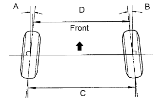
| 3. INSPECT TOE-IN |
|
| Item | Specified Condition |
| Toe-in (total) | A + B: 0°11' +/-10' (0.18° +/-0.17°) C - D: 2.3 +/-1 mm (0.09 +/-0.04 in.) |
| 4. ADJUST TOE-IN |
Inspect the rear No. 1 suspension arm.
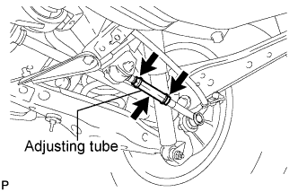 |
Inspect the nuts and adjusting tube for looseness visually and by hand.*1
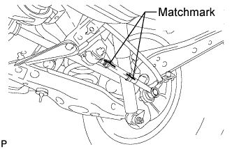 |
Place matchmarks on the arm, nuts and adjusting tube as shown in the illustration.*2
Using SST, apply the specified torque to the adjusting tube in the following order and check that the matchmarks are still aligned: 1) extend direction, 2) contract direction.*3
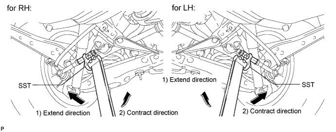
Hold the adjusting tube in place and, using SST, apply the specified torque to the nut on the ball joint side in the following order and check that the matchmarks are still aligned: 1) loosing direction, 2) tightening direction.*4
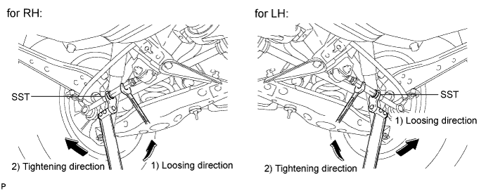
If the adjusting tube or either nut is determined to be loose when performing steps *1 to *4, replace the rear No. 1 suspension arm.
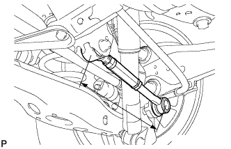 |
Measure the length of the left and right rear No. 1 suspension arms.
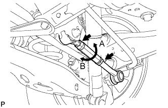 |
Loosen the 2 lock nuts of the adjusting tube.
If the difference between the length of the left and right rear No. 1 suspension arms is not within the specification, adjust the value to within the specification using the method below.
If the toe-in value deviates towards the inside, turn the adjusting tube of the shorter No. 1 suspension arm assembly in the direction which increases arm length until the difference between the left and right suspension arms is within the specification.
If the toe-in value deviates towards the outside, turn the adjusting tube of the longer No. 1 suspension arm assembly in the direction which decreases arm length until the difference between the left and right suspension arms is within the specification.
Measure the toe-in again.
Turn the left and right adjusting tubes in the same direction by the same amount to adjust the toe-in.
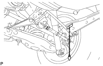 |
Attach a string and weight to the vehicle as shown in the illustration.
Place the vehicle on a level surface, and then check that the string and weight are perpendicular to the vehicle body.
Hold the adjusting tube in place and, using SST, tighten the nut on the ball joint side.*5
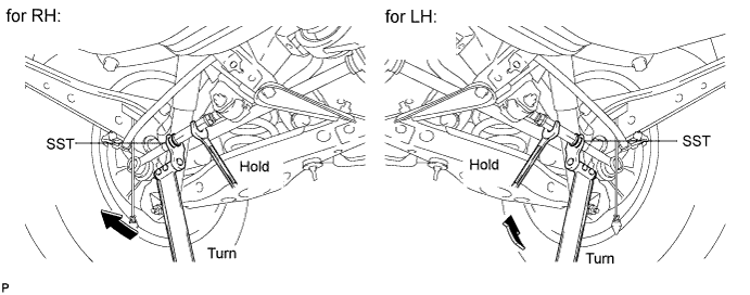
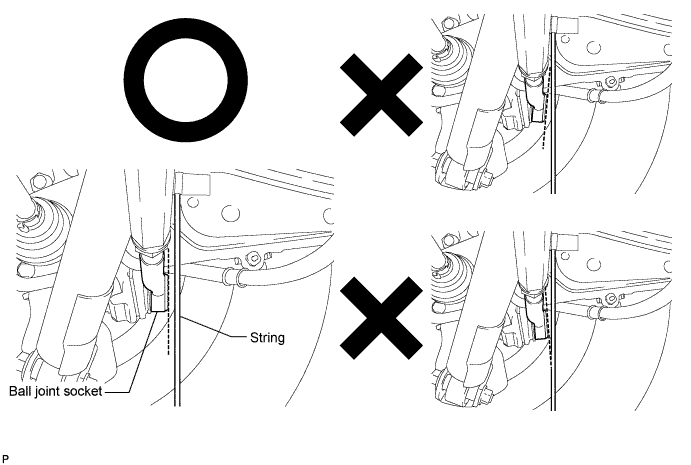
Turn the adjusting tube so that the ball joint socket is parallel to the string as shown in the illustration.*6
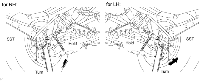
Hold the adjusting tube in place and, using SST, loosen the nut on the ball joint side.*7
Hold the adjusting tube in place and, using SST, tighten the nut on the rubber bush side and nut on the ball joint side in the following order: 1) rubber bush side, 2) ball joint side, 3) rubber bush side.*8
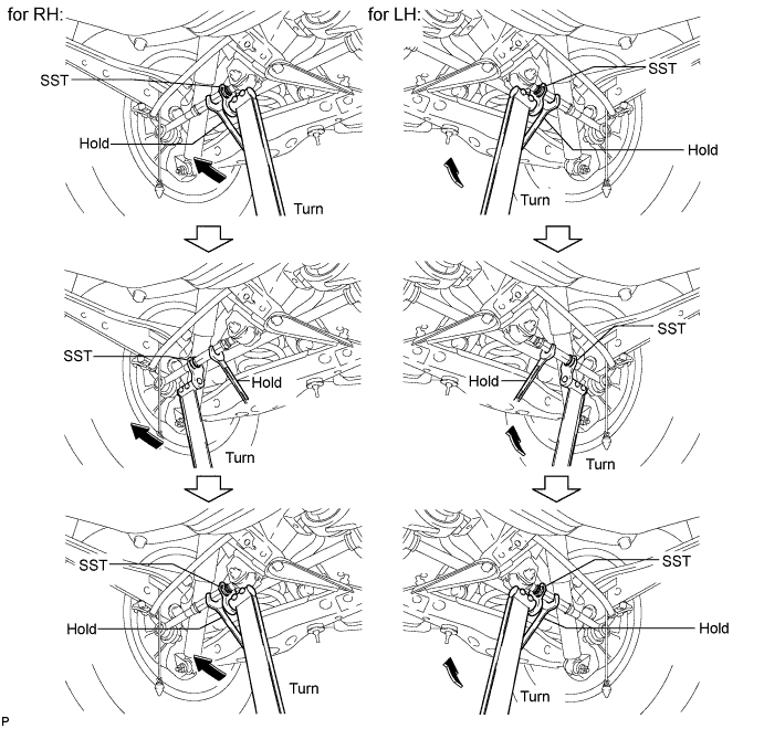
Final check, hold the adjusting tube in place and, using SST, tighten the nut on the rubber bush side and nut on the ball joint side in the following order: 1) rubber bush side, 2) ball joint side, 3) rubber bush side.*9
Check that the ball joint socket is parallel to the string.
Remove the string and weight from the vehicle.
| 5. INSPECT CAMBER |
Install the camber-caster-kingpin gauge or set the vehicle on the wheel alignment tester.
Inspect the camber.
| Item | Specified Condition | |
| Camber Right-left error | *Tire Size: 215/70R16 | -0°58' +/-45' (-0.97° +/-0.75°) 45' (0.75°) or less |
| Tire Size: 225/65R17 Tire Size: 235/55R18 | -1°07' +/-45' (-1.12° +/-0.75°) 45' (0.75°) or less | |
| Australia | -0°52' +/-45' (0.87° +/-0.75°) 45' (0.75°) or less | |