 |
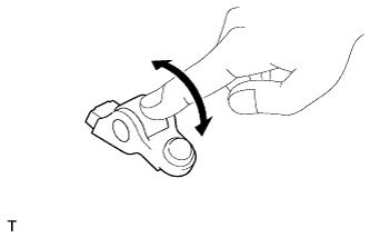
Turn the roller by hand to check that it turns smoothly.
If the roller does not turn smoothly, replace the No. 1 valve rocker arm sub-assembly.
CYLINDER HEAD GASKET > INSTALLATION |
| 1. INSPECT NO. 1 VALVE ROCKER ARM SUB-ASSEMBLY |
|
Turn the roller by hand to check that it turns smoothly.
If the roller does not turn smoothly, replace the No. 1 valve rocker arm sub-assembly.
| 2. INSPECT VALVE LASH ADJUSTER ASSEMBLY |
Place the lash adjuster into a container full of new engine oil.
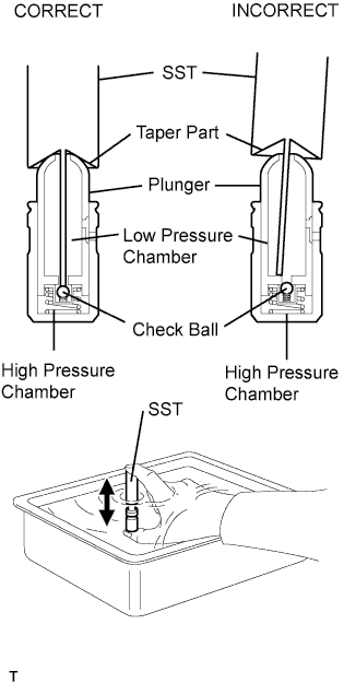 |
Insert the tip of SST into the lash adjuster plunger and use the tip to press down on the check ball inside the plunger.
Squeeze SST and the valve lash adjuster together to move the plunger up and down 5 to 6 times.
Check the movement of the plunger and bleed the air.
After bleeding the air, remove SST. Then try to quickly and firmly press the plunger with your fingers.
| 3. INSPECT CYLINDER HEAD SET BOLT |
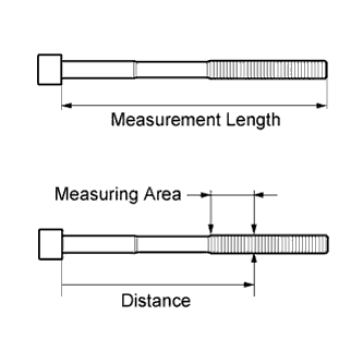 |
Using a vernier caliper, measure the length of the cylinder head bolt from the seat to the end.
Using a vernier caliper, measure the diameter of the elongated thread at the measuring area.
| 4. INSPECT CYLINDER HEAD |
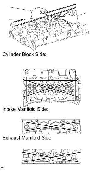 |
Using a precision straightedge and feeler gauge, measure the warpage of the contact surfaces where the cylinder head contacts the cylinder block and manifolds.
| Item | Specified Condition |
| Cylinder Block Side | 0.05 mm (0.00197 in.) |
| Intake Manifold Side | 0.10 mm (0.00394 in.) |
| Exhaust Manifold Side | 0.10 mm (0.00394 in.) |
| 5. INSTALL CYLINDER HEAD GASKET |
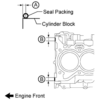 |
Apply seal packing to the cylinder block as shown in the illustration.
| Area | Seal Packing Application Length | Distance from Edge of Cylinder Block to Center of Seal Packing |
| A | - | 2.0 to 4.0 mm (0.0787 to 0.157 in.) |
| B | 10 to 15 mm (0.394 to 0.591 in.) | - |
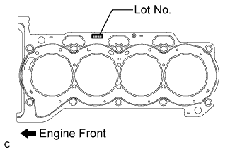 |
Place a new cylinder head gasket on the cylinder block with the Lot No. stamp facing upward.
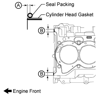 |
Apply seal packing to the cylinder head gasket as shown in the illustration.
| Area | Seal Packing Application Length | Distance from Edge of Cylinder Head Gasket to Center of Seal Packing |
| A | - | 2.0 to 4.0 mm (0.0787 to 0.157 in.) |
| B | 10 to 15 mm (0.394 to 0.591 in.) | - |
| 6. INSTALL CYLINDER HEAD SUB-ASSEMBLY |
Place the cylinder head on the cylinder block.
Install the plate washers to the cylinder head bolts.
Apply a light coat of engine oil to the threads and under the heads of the cylinder head bolts.
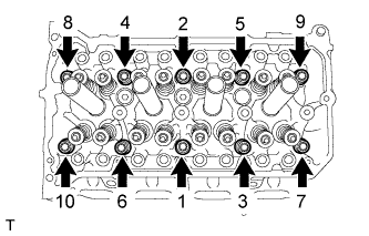 |
Step 1:
Using a 10 mm bi-hexagon wrench, install and uniformly tighten the 10 cylinder head bolts in several steps, in the sequence shown in the illustration.
 |
Step 2:
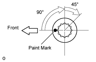
Mark each cylinder head bolt head with paint as shown in the illustration.
Tighten the cylinder head bolts 90° in the sequence shown in step 1.
Step 3:
Tighten the cylinder head bolts another 45° in the sequence shown in step 1.
Check that the paint mark is now at a 135° angle to the front.
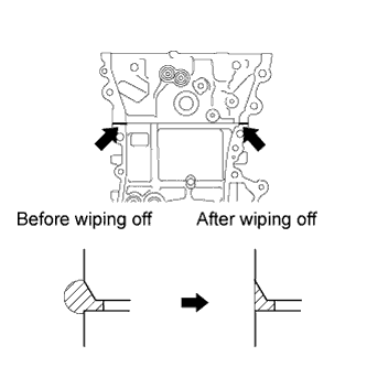 |
After tightening the cylinder head bolts, wipe off the seal packing material that has seeped out from between the contact surfaces of the cylinder head and cylinder block.
| 7. INSTALL VALVE STEM CAP |
Apply a light coat of engine oil to the valve stem ends.
Install the 16 valve stem caps to the cylinder head.
| 8. INSTALL NO. 1 WATER BY-PASS PIPE |
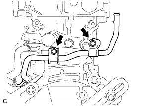 |
Install the water by-pass pipe with the 2 bolts.
| 9. INSTALL EXHAUST MANIFOLD |
Install a new exhaust manifold gasket.
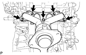 |
Install the exhaust manifold with the 5 nuts.
| 10. INSTALL MANIFOLD STAY |
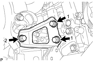 |
Temporarily install the manifold stay with the 3 bolts.
While pushing the manifold stay toward the exhaust manifold, tighten the 2 bolts labeled 1.
Tighten the bolt labeled 2.
| 11. INSTALL NO. 1 EXHAUST MANIFOLD HEAT INSULATOR |
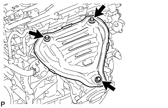 |
Install the heat insulator with the 3 bolts.
| 12. INSTALL CAMSHAFT HOUSING SUB-ASSEMBLY |
Install the camshaft housing sub-assembly (Click here).
| 13. INSTALL ENGINE ASSEMBLY WITH TRANSAXLE |
Install the engine assembly with transaxle (Click here).