 |
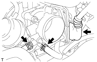
Disconnect the throttle body connector and 2 water hoses.
CAMSHAFT > REMOVAL |
| 1. REMOVE ENGINE ASSEMBLY WITH TRANSAXLE |
Remove the engine assembly with transaxle (Click here).
| 2. REMOVE THROTTLE BODY ASSEMBLY |
|
Disconnect the throttle body connector and 2 water hoses.
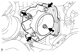 |
Remove the 2 bolts, 2 nuts and throttle body.
Remove the gasket.
| 3. REMOVE INTAKE MANIFOLD |
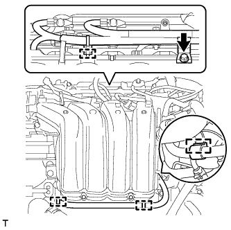 |
Remove the bolt and wire harness clamp bracket.
Detach the 4 clamps and wire harness from the intake manifold.
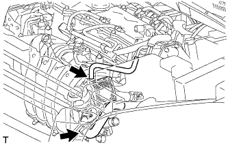 |
Disconnect the fuel vapor feed hose and ventilation hose.
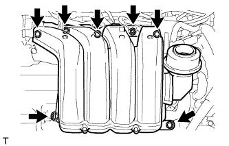 |
Remove the 5 bolts, 2 nuts, intake manifold stay and intake manifold.
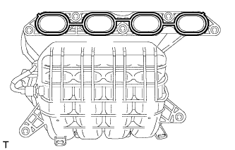 |
Remove the gasket from the intake manifold.
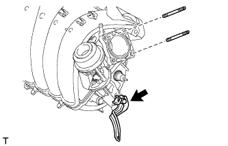 |
Remove the bolt and wire harness clamp bracket from the intake manifold.
Using an E6 "TORX" socket wrench, remove the 2 stud bolts from the intake manifold.
| 4. REMOVE AIR TUBE |
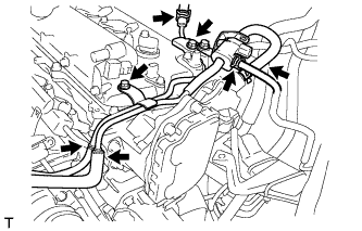 |
Disconnect the fuel vapor feed hose from the purge VSV.
Disconnect the 2 union to connector tube hoses.
Disconnect the No. 2 air hose and No. 1 fuel vapor feed hose.
Remove the 2 bolts and air tube.
| 5. REMOVE WIRE HARNESS CLAMP BRACKET |
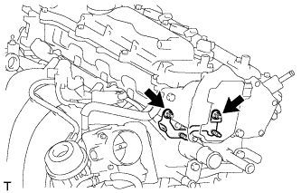 |
Remove the 2 nuts and wire harness clamp bracket.
| 6. REMOVE FUEL TUBE SUB-ASSEMBLY |
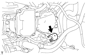 |
Remove the No. 2 fuel pipe clamp.
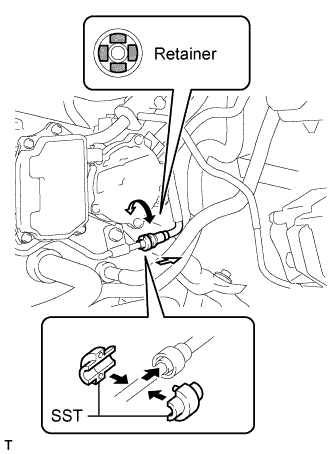 |
Wipe off any dirt on the fuel tube connector.
Hold the fuel tube connector, and then install SST.
Turn SST to align the retainer inside the fuel tube connector with the chamfered part of SST.
Insert SST into the fuel tube and hold it. Then push the fuel tube connector toward SST.
Mount the retainer of the fuel tube connector onto the chamfered part of SST.
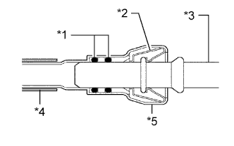 |
Slide SST and the fuel tube connector together towards the fuel tube until they make a "click" sound, and then disconnect the fuel tube.
| *1 | O-Ring |
| *2 | Retainer |
| *3 | Pipe |
| *4 | Nylon Tube |
| *5 | Fuel Tube Connector |
Drain the fuel remaining inside the fuel tube.
Cover the fuel tube and fuel pipe with a plastic bag to protect the disconnected part.
| 7. REMOVE FUEL DELIVERY PIPE SUB-ASSEMBLY |
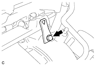 |
Remove the bolt and wire harness bracket.
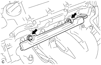 |
Remove the 2 bolts.
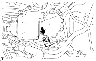 |
Remove the bolt and fuel delivery pipe.
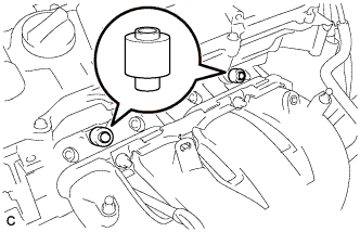 |
Remove the 2 No. 1 delivery pipe spacers.
| 8. REMOVE FUEL INJECTOR ASSEMBLY |
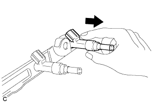 |
Pull the 4 fuel injector assemblies out of the fuel delivery pipe sub-assembly.
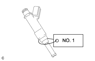 |
For reinstallation, attach a tag or label to the injector shaft.
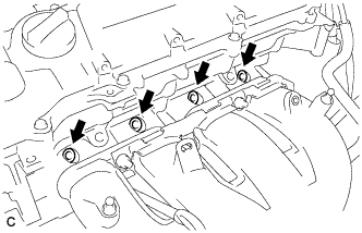 |
Remove the 4 injector vibration insulators.
| 9. REMOVE ENGINE OIL LEVEL DIPSTICK GUIDE |
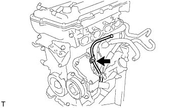 |
Remove the engine oil level dipstick.
Remove the bolt and dipstick guide.
Remove the O-ring from the dipstick guide.
| 10. DISCONNECT NO. 3 WATER BY-PASS HOSE |
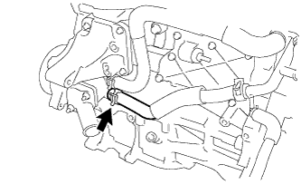 |
Disconnect the No. 3 water by-pass hose from the water inlet housing.
| 11. DISCONNECT WATER INLET HOSE |
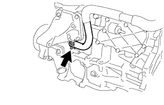 |
Disconnect the water inlet hose from the water inlet housing.
| 12. REMOVE WATER INLET |
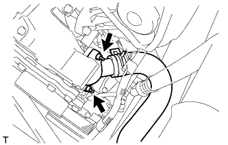 |
Remove the 2 nuts and disconnect the water inlet.
| 13. REMOVE THERMOSTAT |
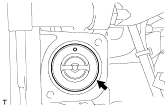 |
Remove the thermostat.
Remove the gasket from the thermostat.
| 14. REMOVE VACUUM PUMP ASSEMBLY |
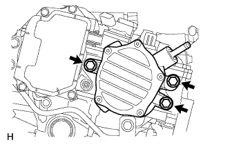 |
Remove the 3 bolts and vacuum pump from the engine.
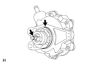 |
Remove the 2 O-rings from the vacuum pump.
| 15. REMOVE NO. 1 VACUUM PUMP BRACKET |
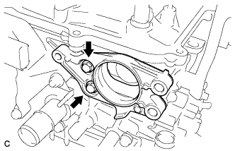 |
Remove the 2 bolts, vacuum pump bracket and gasket.
| 16. REMOVE IGNITION COIL ASSEMBLY |
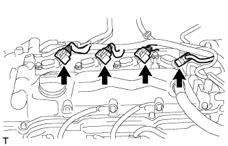 |
Disconnect the 4 ignition coil connectors.
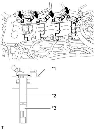 |
Remove the 4 bolts and 4 ignition coils.
| *1 | Cylinder Head Cover |
| *2 | Spark Plug Tube |
| *3 | Plug Cap |
| 17. REMOVE RADIO SETTING CONDENSER |
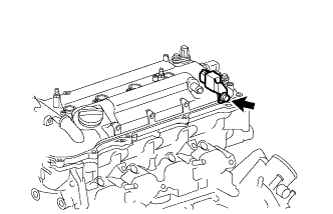 |
Remove the bolt and setting condenser.
| 18. REMOVE CYLINDER HEAD COVER SUB-ASSEMBLY |
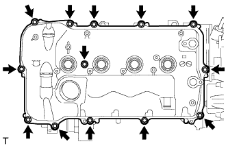 |
Remove the 13 bolts, seal washer and cylinder head cover.
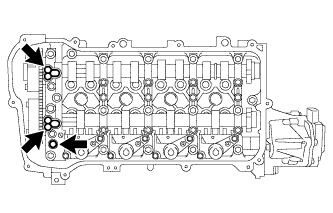 |
Remove the 3 gaskets from the camshaft bearing cap.
| 19. REMOVE CYLINDER HEAD COVER GASKET |
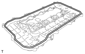 |
Remove the cylinder head cover gasket.
| 20. REMOVE SPARK PLUG TUBE GASKET |
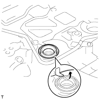 |
Pry up the 4 claws of the ventilation baffle plate.
Remove the 4 gaskets from the cylinder head cover.
| 21. SET NO. 1 CYLINDER TO TDC/COMPRESSION |
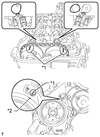 |
Turn the crankshaft pulley until its notch and timing mark "0" of the timing chain cover are aligned.
| *1 | Timing Mark |
| *2 | Timing Notch |
Check that timing marks on both the camshaft timing exhaust gear and camshaft timing gear are facing upward as shown in the illustration.
| 22. REMOVE CRANKSHAFT PULLEY |
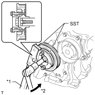 |
Using SST, hold the crankshaft pulley and loosen the pulley bolt. Further loosen the bolt until 2 or 3 threads are screwed into the crankshaft.
| *1 | Hold |
| *2 | Turn |
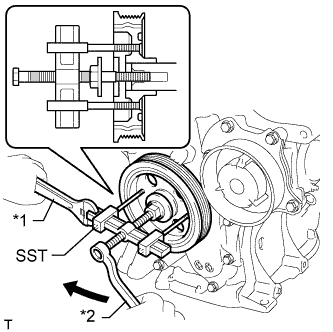 |
Using SST and the pulley bolt, remove the crankshaft pulley and pulley bolt.
| *1 | Hold |
| *2 | Turn |
| 23. REMOVE NO. 1 CHAIN TENSIONER ASSEMBLY |
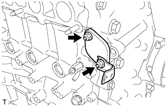 |
Remove the 2 nuts, bracket, chain tensioner and gasket.
| 24. REMOVE TIMING CHAIN COVER SUB-ASSEMBLY |
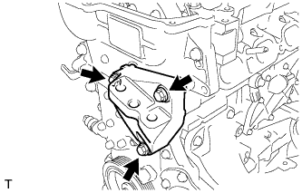 |
Remove the 3 bolts and engine mounting bracket.
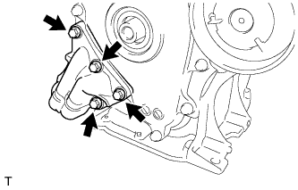 |
Remove the 4 bolts and oil filter bracket.
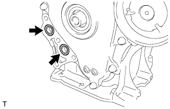 |
Remove the 2 O-rings.
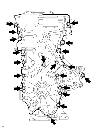 |
Remove the 19 bolts.
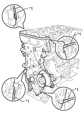 |
Remove the timing chain cover by prying between the timing chain cover and cylinder head, camshaft housing, cylinder block and stiffening crankcase with a screwdriver as shown in the illustration.
| *1 | Protective Tape |
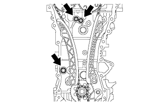 |
Remove the 3 O-rings.
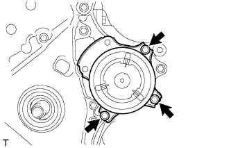 |
Remove the 3 bolts and water pump.
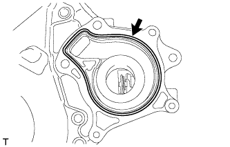 |
Remove the gasket.
| 25. REMOVE TIMING CHAIN COVER OIL SEAL |
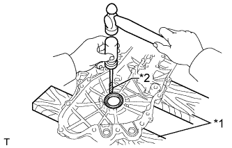 |
Place the timing chain cover on wooden blocks.
| *1 | Wooden Block |
| *2 | Protective Tape |
Using a screwdriver, tap out the oil seal.
| 26. REMOVE CHAIN TENSIONER SLIPPER |
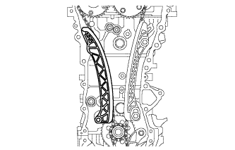 |
Remove the chain tensioner slipper from the cylinder block.
| 27. REMOVE NO. 1 CHAIN VIBRATION DAMPER |
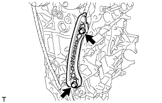 |
Remove the 2 bolts and chain vibration damper.
| 28. REMOVE CHAIN SUB-ASSEMBLY |
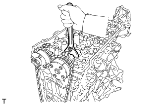 |
Hold the hexagonal portion of the camshaft with a wrench and turn the camshaft timing gear counterclockwise to loosen the chain between the camshaft timing gears.
With the chain loosened, release the chain from the camshaft timing gear and place it on the camshaft timing gear.
Turn the camshaft clockwise to return it to the original position and remove the chain.
| 29. INSPECT CAMSHAFT TIMING GEAR ASSEMBLY |
Check the lock of the camshaft timing gear.
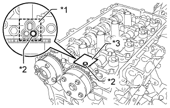 |
After cleaning and degreasing the VVT oil hole on the intake side of the No. 1 camshaft bearing cap, completely seal the oil hole with adhesive tape or equivalent as shown in the illustration to prevent air from leaking.
| *1 | Adhesive Tape Sealing Area |
| *2 | Prick a Hole |
| *3 | Adhesive Tape |
Prick a hole in the tape covering the oil hole as shown in the illustration. (Procedure A)
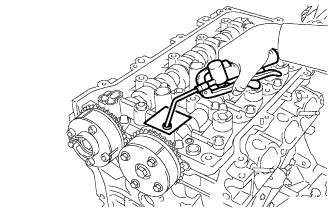 |
Apply approximately 150 kPa (1.5 kgf/cm2, 22 psi) of air pressure to the hole pricked in procedure A to release the lock pin.
Forcibly turn the camshaft timing gear in the advance direction (counterclockwise).
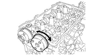 |
Turn the camshaft timing gear within its movable range (26.5 to 28.5°) 2 or 3 times without turning it to the most retarded position. Make sure that the camshaft timing gear turns smoothly.
Remove the adhesive tape from the No. 1 camshaft bearing cap.
| 30. INSPECT CAMSHAFT TIMING EXHAUST GEAR ASSEMBLY |
Check the lock of the camshaft timing exhaust gear.
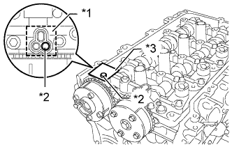 |
After cleaning and degreasing the VVT oil hole on the exhaust side of the No. 1 camshaft bearing cap, completely seal the oil hole with adhesive tape or equivalent as shown in the illustration to prevent air from leaking.
| *1 | Adhesive Tape Sealing Area |
| *2 | Prick a Hole |
| *3 | Adhesive Tape |
Prick a hole in the tape covering the oil hole as shown in the illustration. (Procedure A)
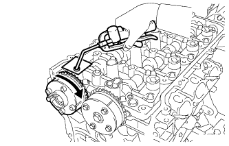 |
Apply approximately 200 kPa (2.0 kgf/cm2, 28 psi) of air pressure to the hole pricked in procedure A to release the lock pin.
Using a screwdriver with its tip wrapped with tape, forcibly turn the camshaft timing exhaust gear in the retard direction (clockwise).
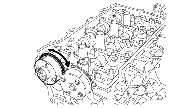 |
Using a screwdriver with its tip wrapped with tape, turn the camshaft timing exhaust gear within its movable range (19 to 21°) 2 or 3 times without turning it to the most advanced position. Make sure that the camshaft timing exhaust gear turns smoothly.
Remove the adhesive tape from the No. 1 camshaft bearing cap.
| 31. REMOVE CAMSHAFT TIMING GEAR ASSEMBLY |
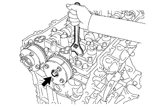 |
Remove the flange bolt while holding the hexagonal portion of the camshaft, and then remove the camshaft timing gear.
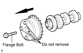 |
| 32. REMOVE CAMSHAFT TIMING EXHAUST GEAR ASSEMBLY |
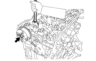 |
Remove the flange bolt while holding the hexagonal portion of the camshaft, and then remove the camshaft timing exhaust gear.
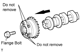 |
| 33. REMOVE VALVE ROCKER ARM LOST MOTION DAMPER SUB-ASSEMBLY |
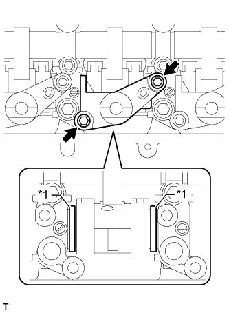 |
Remove the 2 bolts and valve rocker arm lost motion damper.
| *1 | Shim |
| 34. INSTALL VALVE ROCKER ARM LOST MOTION DAMPER SUB-ASSEMBLY |
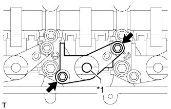 |
Install the valve rocker arm lost motion damper with the 2 bolts. Uniformly tighten the bolts.
Add engine oil into the hole for engine oil.
| *1 | Hole for Engine Oil |
| 35. REMOVE CAMSHAFT HOUSING SUB-ASSEMBLY |
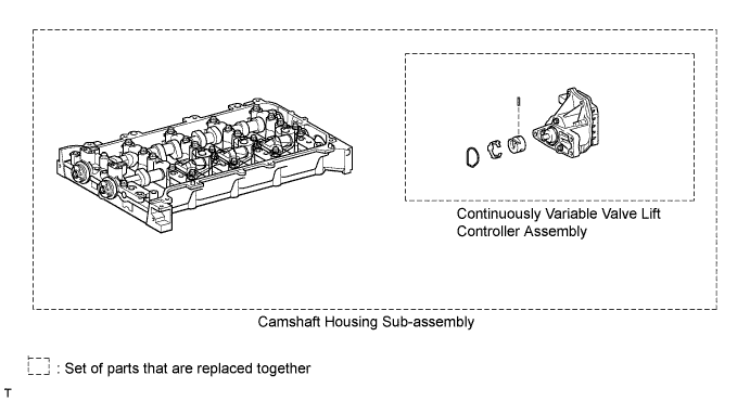
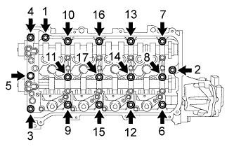 |
Uniformly loosen and remove the 17 bearing cap bolts in the sequence shown in the illustration.
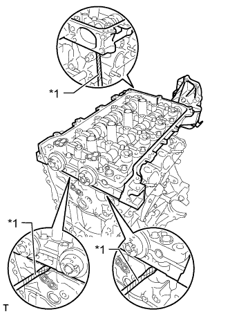 |
Remove the camshaft housing by prying between the cylinder head and camshaft housing with a screwdriver.
| *1 | Protective Tape |
| 36. REMOVE NO. 1 VALVE ROCKER ARM SUB-ASSEMBLY |
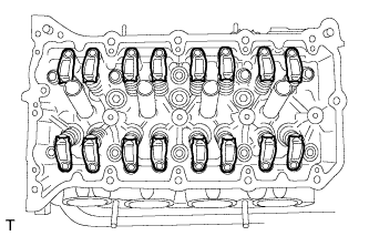 |
Remove the 16 valve rocker arms.
| 37. REMOVE VALVE LASH ADJUSTER ASSEMBLY |
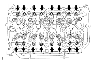 |
Remove the 16 valve lash adjusters from the cylinder head.
| 38. INSPECT NO. 1 VALVE ROCKER ARM SUB-ASSEMBLY |
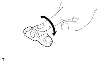 |
Turn the roller by hand to check that it turns smoothly.
If the roller does not turn smoothly, replace the No. 1 valve rocker arm sub-assembly.
| 39. INSPECT VALVE LASH ADJUSTER ASSEMBLY |
Place the lash adjuster into a container full of new engine oil.
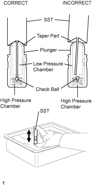 |
Insert the tip of SST into the lash adjuster plunger and use the tip to press down on the check ball inside the plunger.
Squeeze SST and the valve lash adjuster together to move the plunger up and down 5 to 6 times.
Check the movement of the plunger and bleed the air.
After bleeding the air, remove SST. Then try to quickly and firmly press the plunger with your fingers.