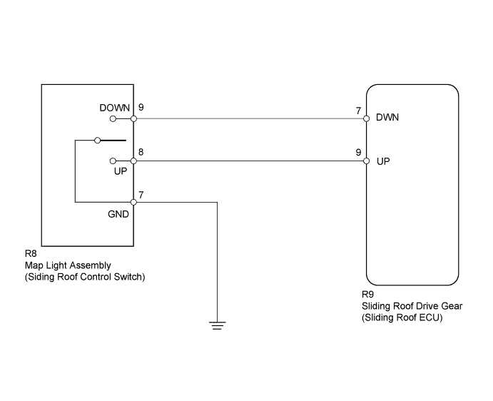
DTC B2341 Sensor (Motor) Failure |
DTC B2344 Position Failure |
| DTC Code | DTC Detection Condition | Trouble Area |
| B2341 | Sensor (motor) Failure |
|
| B2344 | Position Failure |
|
| 1.CHECK SLIDING ROOF FUNCTION |
Check the auto operation with the SLIDE OPEN and TILT UP switch (Click here).
|
| ||||
| OK | |
 |
| 2.DELETE DTC |
Delete the DTC (Click here).
| NEXT | ||
 | ||
| ||
| 3.INITIALIZE SLIDING ROOF DRIVE GEAR SUB-ASSEMBLY (SLIDING ROOF ECU) |
Check that the sliding roof drive gear can be initialized (Click here).
|
| ||||
| OK | |
|
| 4.CHECK SLIDING ROOF FUNCTION |
Check the auto operation with the SLIDE OPEN and TILT UP switch (Click here).
|
| ||||
| OK | |
|
| 5.DELETE DTC |
Delete the DTC (Click here).
| NEXT | |
|
| 6.CHECK WIRE HARNESS (SLIDING ROOF DRIVE GEAR - MAP LIGHT ASSEMBLY) |
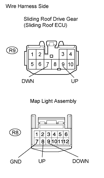 |
Disconnect the R9 gear connector.
Disconnect the R8 map light connector.
Measure the resistance of the wire harness side connectors.
| Tester Connection | Specified Condition |
| R9-7 (DWN) - R8-9 (DOWN) | Below 1 Ω |
| R9-9 (UP) - R8-8 (UP) | Below 1 Ω |
| R8-7 (GND) - Body ground | Below 1 Ω |
| R9-7 (DWN) - Body ground | 10 kΩ or higher |
| R9-9 (UP) - Body ground | 10 kΩ or higher |
|
| ||||
| OK | |
|
| 7.INSPECT MAP LIGHT ASSEMBLY (SLIDING ROOF CONTROL SWITCH) |
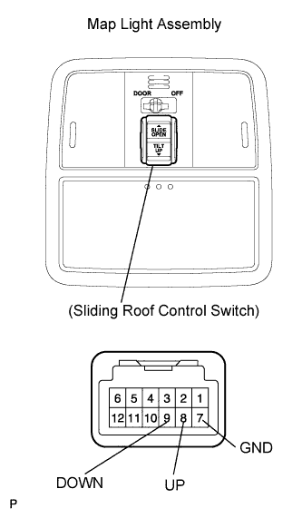 |
Remove the map light assembly.
Measure the resistance of the switch.
| Tester Connection | Switch Condition | Specified Condition |
| 8 (UP) - 7 (GND) | TILT UP switch pushed | Below 1 Ω |
| 8 (UP) - 7 (GND) | TILT UP switch not pushed | 10 kΩ or higher |
| 9 (DOWN) - 7 (GND) | SLIDE OPEN switch pushed | Below 1 Ω |
| 9 (DOWN) - 7 (GND) | SLIDE OPEN switch not pushed | 10 kΩ or higher |
|
| ||||
| OK | ||
| ||
| ||

