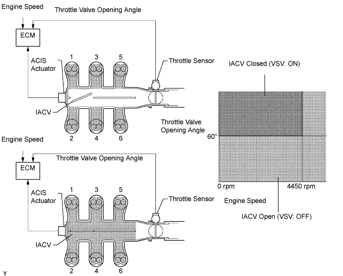
DTC P0660 Intake Manifold Tuning Valve Control Circuit / Open (Bank 1) |
| DTC No. | DTC Detection Condition | Trouble Area |
| P0660 | The following conditions are met simultaneously for 0.5 seconds or more (2 trip detection logic):
|
|
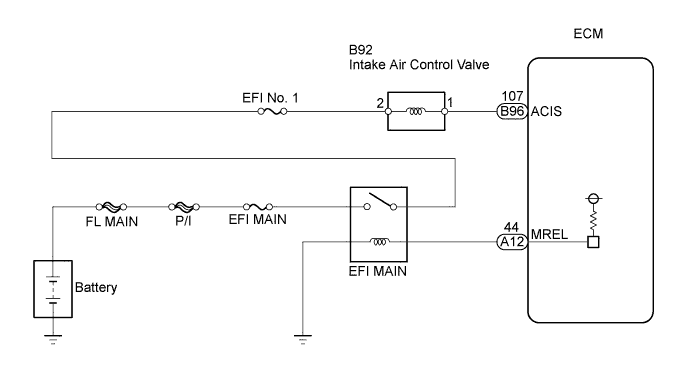
| 1.PERFORM ACTIVE TEST USING INTELLIGENT TESTER |
Connect the intelligent tester to the DLC3.
Start the engine and turn the tester on.
Select the following menu items: Powertrain / Engine and ECT / Active Test / Active the VSV for Intake Control.
Check if operating noise can be heard when operating the air intake control valve using the intelligent tester.
|
| ||||
| NG | |
 |
| 2.CHECK INTAKE AIR CONTROL VALVE (ACIS OPERATION) |
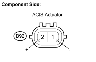 |
Disconnect the ACIS actuator connector.
Apply battery voltage between the terminals of the ACIS actuator connector.
Check intake air control valve operation.
|
| ||||
| OK | |
|
| 3.INSPECT ACIS ACTUATOR (POWER SOURCE) |
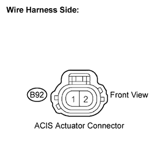 |
Disconnect the ACIS actuator connector.
Turn the ignition switch to the ON position.
Measure the voltage between the terminals of the AICS actuator connector.
| Tester Connection | Specified Condition |
| 1 - 2 | 9 to 14 V |
|
| ||||
| OK | |
|
| 4.CHECK HARNESS AND CONNECTOR |
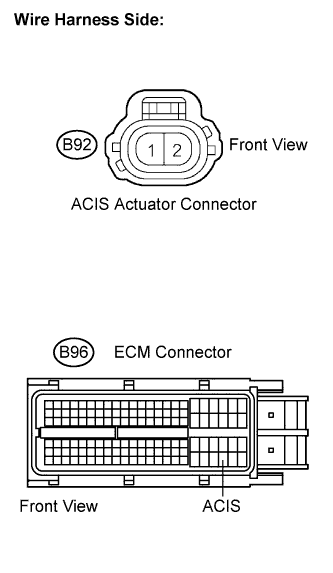 |
Disconnect the ACIS actuator connector.
Disconnect the ECM connector.
Measure the resistance between the terminals of the ACIS connector and ECM connector.
| Tester Connection | Specified Condition |
| ACIS actuator (B92-1) - ACIS (B96-107) | Below 1 Ω |
| Tester Connection | Specified Condition |
| ACIS actuator (B92-1) or ACIS (B96-107) - Body ground | 10 kΩ or higher |
Reconnect the ECM connector.
Reconnect the ACIS connector.
|
| ||||
| OK | ||
 | ||
| ||
