INTAKE MANIFOLD > INSTALLATION |
| 1. INSTALL NO. 1 GAS FILTER |
|
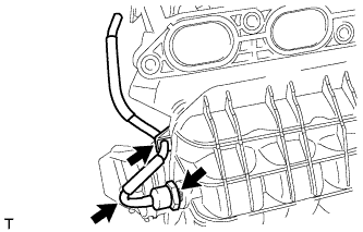
Using a 24 mm deep socket wrench, install the gas filter to the intake manifold.
Connect the air hose.
| 2. INSTALL INTAKE MANIFOLD |
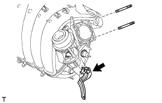 |
Using an E6 "TORX" socket wrench, install the 2 stud bolts to the intake manifold.
Install the wire harness clamp bracket to the intake manifold with the bolt.
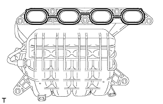 |
Install a new gasket to the intake manifold.
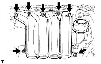 |
Install the intake manifold and intake manifold stay with the 5 bolts and 2 nuts.
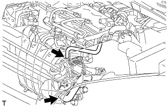 |
Connect the fuel vapor feed hose and ventilation hose.
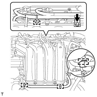 |
Attach the 4 clamps to the intake manifold.
Install the wire harness clamp bracket with the bolt.
| 3. INSTALL ENGINE COVER JOINT |
Install the engine cover joint.
| 4. INSTALL VACUUM SWITCHING VALVE ASSEMBLY (for ACIS) |
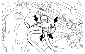 |
Install the vacuum switching valve with the bolt.
Connect the connector and 2 vacuum hoses.
| 5. INSTALL VACUUM SENSOR ASSEMBLY |
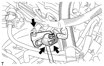 |
Connect the air hose to the vacuum sensor.
Install the vacuum sensor with the engine cover joint.
Connect the vacuum sensor connector.
| 6. INSTALL UPPER RADIATOR SUPPORT SUB-ASSEMBLY |
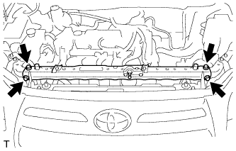 |
Install the upper radiator support with the 4 bolts.
Connect the 3 water by-pass hoses to the No. 1 water by-pass pipe.
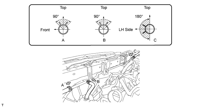
w/ Hood Courtesy Switch:
Attach the wire harness clamp to the upper radiator support.
Attach the clamp to connect the hood lock cable.
| 7. INSTALL UPPER RADIATOR SUPPORT BRACKET |
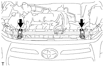 |
Install the 2 upper radiator support brackets with the 2 bolts.
| 8. INSTALL HOOD LOCK ASSEMBLY |
for LHD:
Install the hood lock .
for RHD:
Install the hood lock .
| 9. INSTALL THROTTLE BODY ASSEMBLY |
Install a new gasket into the intake manifold.
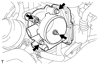 |
Install the throttle body with the 2 bolts and 2 nuts.
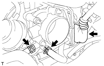 |
Connect the throttle body connector and 2 water hoses.
| 10. INSTALL AIR CLEANER CAP SUB-ASSEMBLY |
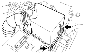 |
Insert the hinge part of the air cleaner cap and hose into the air cleaner case, and then fasten the 2 hook clamps.
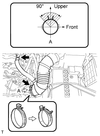 |
Connect the No. 1 air cleaner hose to the throttle body and push apart the tabs of the No. 1 air cleaner hose clamp.
Connect the No. 2 ventilation hose to the cylinder head cover.
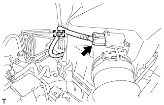 |
Attach the clamp.
Connect the mass air flow meter connector.
| 11. INSTALL GENERATOR ASSEMBLY |
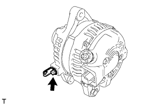 |
Install the wire harness clamp bracket with the bolt.
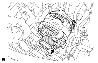 |
Temporarily install the generator with the bolt.
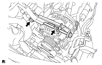 |
Temporarily install the adjusting bar with the 2 bolts.
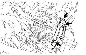 |
Install the wire harness to terminal B with the nut.
Install the terminal cap.
Connect the connector and wire harness clamp.
Install V-ribbed belt .
Adjust V-ribbed belt .
Inspect V-ribbed belt .
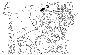 |
Tighten the bolt.
| 12. INSTALL V-RIBBED BELT |
Temporarily install the V-ribbed belt.
| 13. ADJUST V-RIBBED BELT |
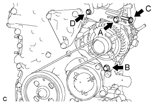 |
Turn bolt C to adjust the tension of the V-ribbed belt.
Tighten bolts A and B.
| 14. INSPECT V-RIBBED BELT |
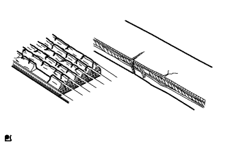 |
Check the belt for wear, cracks or other signs of damage.
If any of the following defects is found, replace the V-ribbed belt.
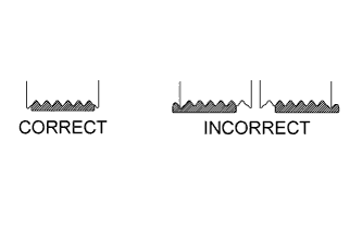 |
Check that the belt fits properly in the ribbed grooves.
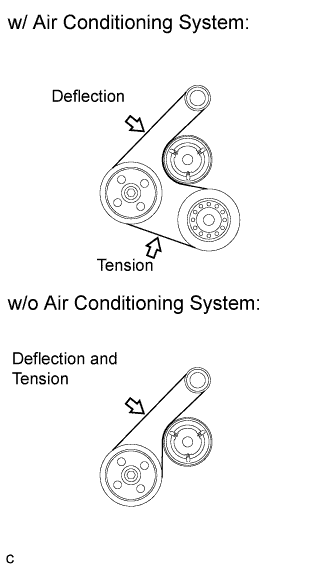 |
Check the V-ribbed belt deflection and tension.
| Item | Specified Condition |
| New belt | 7.0 to 8.2 mm (0.276 to 0.323 in.) |
| Used belt | 7.6 to 10.0 mm (0.299 to 0.394 in.) |
| Item | Specified Condition |
| New belt | 700 to 800 N (70 to 80 kgf, 157.4 to 179.8 lbf) |
| Used belt | 550 to 750 N (55 to 75 kgf, 123.6 to 168.6 lbf) |
| 15. INSTALL REAR ENGINE UNDER COVER RH |
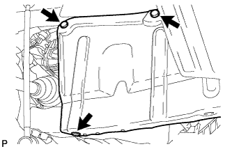 |
Install the under cover with the 3 clips.
| 16. INSTALL FLYWHEEL HOUSING SIDE COVER |
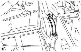 |
Install the flywheel housing side cover to the cylinder block.
| 17. INSTALL STARTER ASSEMBLY |
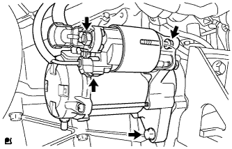 |
Install the starter with the 2 bolts.
Connect the starter connector.
Connect starter wire with the nut.
Connect the terminal cap.
| 18. CONNECT CABLE TO NEGATIVE BATTERY TERMINAL |
| 19. ADD ENGINE COOLANT |
Tighten the radiator drain cock plug by hand.
Tighten the water drain cock plug.
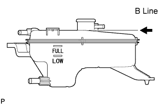 |
Add TOYOTA Super Long Life Coolant (SLLC) to the radiator reservoir filler opening until it is filled to the B line at the base of the reservoir filler neck.
| Item | Specified Condition |
| for Manual Transaxle | 5.8 liters (6.1 US qts, 5.1 Imp. qts) |
| for CVT | 6.0 liters (6.3 US qts, 5.3 Imp. qts) |
Press the No. 1 and No. 2 radiator hoses several times by hand, and then check the level of the coolant. If the coolant level drops below the B line, add TOYOTA SLLC to the B line.
Install the radiator reservoir cap.
Start the engine and warm it up until the cooling fan operates.
Set the air conditioning as follows while warming up the engine.
| Item | Condition |
| Manual Air Conditioning System | Fan speed: Any setting except off Temperature: Toward WARM Air conditioning switch: Off |
| Automatic Air Conditioning System | Temperature: Toward MAX (HOT) Air conditioning switch: Off |
Maintain the engine speed at 2000 to 2500 rpm and warm up the engine until the cooling fan operates.
Press the No. 1 and No. 2 radiator hoses several times by hand to bleed air.
Stop the engine and wait until the coolant cools down to ambient temperature.
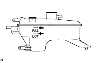 |
Check that the coolant level is between the FULL and LOW lines. If the coolant level is below the LOW line, repeat all of the procedures above.
If the coolant level is above the FULL line, drain coolant so that the coolant level is between the FULL and LOW lines.
| 20. INSPECT FOR COOLANT LEAK |
Remove the radiator reservoir cap.
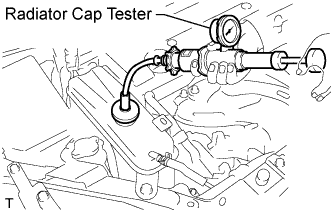 |
Fill the radiator and reservoir with coolant, and then attach a radiator cap tester.
Warm up the engine.
Pump the radiator cap tester to 118 kPa (1.2 kgf/cm2, 17.1 psi), and then check that the pressure does not drop.
If the pressure drops, check the hoses, radiator and water pump for leakage.
If there are no signs of external coolant leaks, check the heater core, cylinder block and head.
Reinstall the radiator reservoir cap.
| 21. INSPECT HOOD SUB-ASSEMBLY |
Check that the clearance measurements of areas A to J are within the standard range.
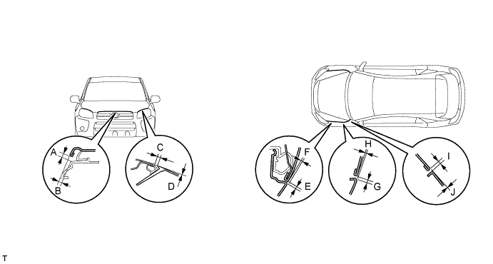
| Area | Specified Condition | Area | Specified Condition |
| A | 7.1 +- 2.5 mm (0.278 +- 0.098 in.) | F | 0.6 +- 1.5 mm (0.024 +- 0.059 in.) |
| B | 3.6 +- 2.5 mm (0.140 +- 0.098 in.) | G | 3.5 +- 1.5 mm (0.138 +- 0.059 in.) |
| C | 5.9 +- 2.5 mm (0.230 +- 0.098 in.) | H | 0.5 +- 1.5 mm (0.020 +- 0.059 in.) |
| D | 0.2 +- 2.5 mm (0.006 +- 0.098 in.) | I | 3.5 +- 1.5 mm (0.138 +- 0.059 in.) |
| E | 3.5 +- 1.5 mm (0.138 +- 0.059 in.) | J | 0.0 +- 1.5 mm (0.000 +- 0.059 in.) |
| 22. ADJUST HOOD SUB-ASSEMBLY |
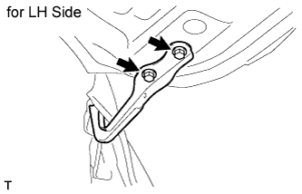 |
Adjust the hood's position.
Loosen the hood's 4 hinge bolts.
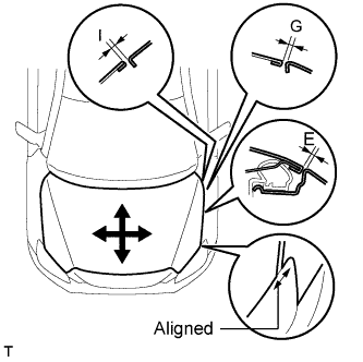 |
Move the hood and adjust the clearance between the hood and front fender. Make sure that the clearance is within the standard range.
| Area | Specified Condition |
| E | 3.5 +- 1.5 mm (0.138 +- 0.059 in.) |
| G | 3.5 +- 1.5 mm (0.138 +- 0.059 in.) |
| I | 3.5 +- 1.5 mm (0.138 +- 0.059 in.) |
Tighten the hood's 4 hinge bolts after the adjustment.
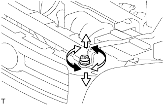 |
Adjust the cushion rubber so that the height of the hood and fender are aligned.
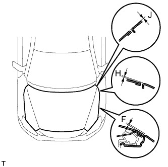 |
Raise or lower the hood's front end by turning the cushion rubber. Make sure that the clearance is within the standard range.
| Area | Specified Condition |
| F | 0.6 +- 1.5 mm (0.024 +- 0.059 in.) |
| H | 0.5 +- 1.5 mm (0.020 +- 0.059 in.) |
| J | 0.0 +- 1.5 mm (0.000 +- 0.059 in.) |
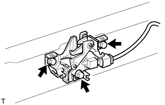 |
Adjust the hood lock.
Loosen the 3 bolts.
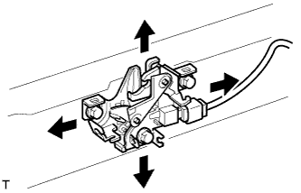 |
Adjust the hood lock position so that the striker can enter it smoothly.
Tighten the 3 bolts after the adjustment.
| 23. INSTALL NO. 1 ENGINE UNDER COVER |
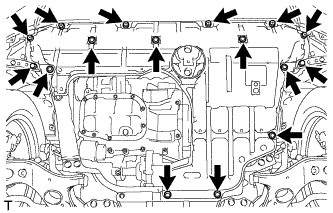 |
Install the under cover with the 6 screws and 10 clips.
| 24. INSTALL NO. 2 CYLINDER HEAD COVER |
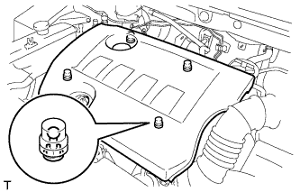 |
Attach the 4 clips to install the cover.
| 25. INSTALL RADIATOR SUPPORT OPENING COVER |
Install the radiator support opening cover with the 9 clips.