 |
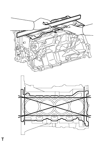
Using a straightedge and feeler gauge, measure the warpage of the surface that contacts the cylinder head gasket.
- Maximum warpage:
- 0.05 mm (0.00197 in.)
CYLINDER BLOCK > INSPECTION |
| 1. INSPECT CYLINDER BLOCK FOR WARPAGE |
|
Using a straightedge and feeler gauge, measure the warpage of the surface that contacts the cylinder head gasket.
| 2. INSPECT CYLINDER BORE |
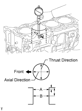 |
Using a cylinder gauge, measure the cylinder bore diameter at positions A and B in both the thrust and axial directions.
| Measurement Position | Cylinder Bore Position |
| A | 10 mm (0.394 in.) from top edge |
| B | 50 mm (1.97 in.) from top edge |
| 3. INSPECT PISTON |
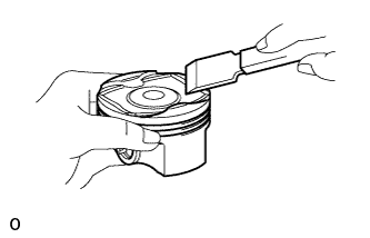 |
Using a gasket scraper, remove the carbon from the piston top.
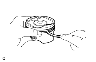 |
Using a groove cleaning tool or broken ring, clean the piston ring grooves.
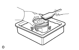 |
Using a brush and solvent, thoroughly clean the piston.
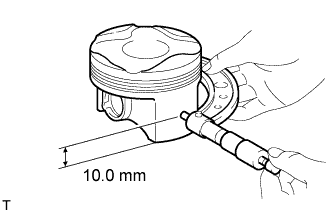 |
Using a micrometer, measure the piston diameter at a position that is 10.0 mm (0.394 in.) from the bottom of the piston (refer to the illustration).
| 4. INSPECT PISTON OIL CLEARANCE |
Subtract the piston diameter measurement from the cylinder bore diameter measurement.
| 5. INSPECT RING GROOVE CLEARANCE |
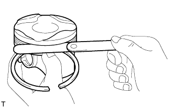 |
Using a feeler gauge, measure the clearance between a new piston ring and the wall of the ring groove.
| Item | Specified Condition |
| No. 1 Compression Ring | 0.02 to 0.07 mm (0.000787 to 0.00276 in.) |
| No. 2 Compression Ring | 0.02 to 0.06 mm (0.000787 to 0.00236 in.) |
| Oil Ring | 0.02 to 0.065 mm (0.000787 to 0.00256 in.) |
| 6. INSPECT PISTON RING END GAP |
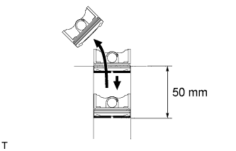 |
Using a piston, push the piston ring a little beyond the bottom of the ring travel, 50 mm (1.97 in.) from the top of the cylinder block.
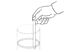 |
Using a feeler gauge, measure the end gap.
| Item | Specified Condition |
| No. 1 Compression Ring | 0.20 to 0.30 mm (0.00787 to 0.0118 in.) |
| No. 2 Compression Ring | 0.30 to 0.50 mm (0.0118 to 0.0197 in.) |
| Oil Ring | 0.10 to 0.40 mm (0.00394 to 0.0157 in.) |
| Item | Specified Condition |
| No. 1 Compression Ring | 0.50 mm (0.0197 in.) |
| No. 2 Compression Ring | 0.70 mm (0.0276 in.) |
| Oil Ring | 0.70 mm (0.0276 in.) |
| 7. INSPECT PISTON PIN OIL CLEARANCE |
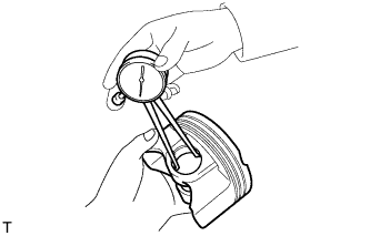 |
Using a caliper gauge, measure the piston pin bore diameter.
| Item | Specified Condition |
| Mark A | 20.006 to 20.009 mm (0.78764 to 0.78775 in.) |
| Mark B | 20.010 to 20.012 mm (0.78779 to 0.78787 in.) |
| Mark C | 20.013 to 20.015 mm (0.78791 to 0.78799 in.) |
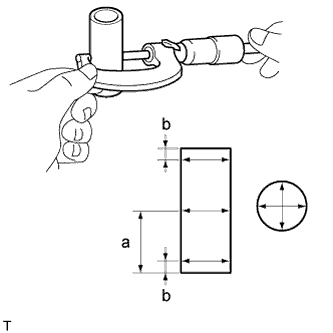 |
Using a micrometer, measure the piston pin diameter.
| Item | Specified Condition |
| Mark A | 20.004 to 20.007 mm (0.78756 to 0.78768 in.) |
| Mark B | 20.008 to 20.010 mm (0.78771 to 0.78779 in.) |
| Mark C | 20.011 to 20.013 mm (0.78783 to 0.78791 in.) |
| Measurement Position | Piston Pin Position |
| a | 25 mm (0.984 in.) from side edge |
| b | 5 mm (0.197 in.) from side edge |
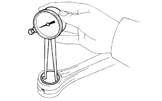 |
Using a caliper gauge, measure the connecting rod small end bore diameter.
| Item | Specified Condition |
| Mark A | 20.012 to 20.015 mm (0.78787 to 0.78799 in.) |
| Mark B | 20.016 to 20.018 mm (0.78803 to 0.78811 in.) |
| Mark C | 20.019 to 20.021 mm (0.78815 to 0.78823 in.) |
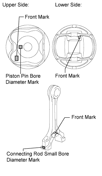 |
Subtract the piston pin diameter measurement from the piston pin bore diameter measurement.
Subtract the piston pin diameter measurement from the connecting rod small end bore diameter measurement.
| 8. INSPECT CONNECTING ROD SUB-ASSEMBLY |
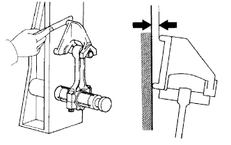 |
Using a connecting rod aligner and feeler gauge, check the connecting rod alignment.
Check for misalignment.
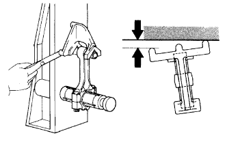 |
Check for twist.
| 9. INSPECT CRANKSHAFT |
Inspect the circle runout.
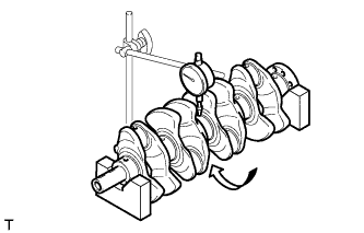 |
Using a dial indicator and V-blocks, measure the circle runout as shown in the illustration.
Inspect the main journals.
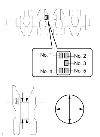 |
Using a micrometer, measure the diameter of each main journal.
Check each main journal for taper and distortion as shown in the illustration.
| Item | Specified Condition |
| Mark 0 | 47.999 to 48.000 mm (1.88972 to 1.88976 in.) |
| Mark 1 | 47.997 to 47.998 mm (1.88964 to 1.88968 in.) |
| Mark 2 | 47.995 to 47.996 mm (1.88956 to 1.88960 in.) |
| Mark 3 | 47.993 to 47.994 mm (1.88948 to 1.88952 in.) |
| Mark 4 | 47.991 to 47.992 mm (1.88941 to 1.88945 in.) |
| Mark 5 | 47.988 to 47.990 mm (1.88929 to 1.88937 in.) |
Inspect the crank pins.
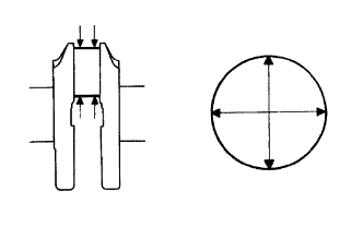 |
Using a micrometer, measure the diameter of each crank pin.
Inspect each crank pin for taper and distortion.
| 10. INSPECT CRANKSHAFT OIL CLEARANCE |
Check the crankshaft journals and bearings for pitting and scratches.
Install the crankshaft bearings .
Install the upper crankshaft thrust washers .
Clean each main journal and bearing.
Place the crankshaft on the cylinder block.
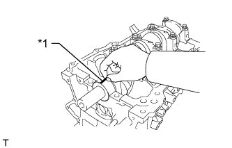 |
Lay a strip of Plastigage across each journal.
| *1 | Plastigage |
Examine the front marks and numbers and place the bearing caps on the cylinder block.
Install the crankshaft bearing caps .
Remove the crankshaft bearing caps .
Measure the Plastigage at its widest point.
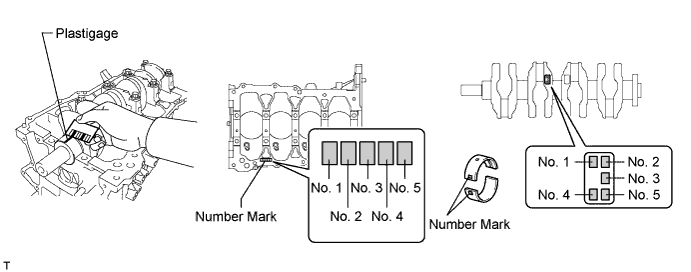
| Cylinder Block + Crankshaft | Bearing to be Used |
| 0 to 2 | "1" |
| 3 to 5 | "2" |
| 6 to 8 | "3" |
| 9 to 11 | "4" |
| Item | Specified Condition |
| Mark 0 | 52.000 to 52.002 mm (2.04724 to 2.04732 in.) |
| Mark 1 | 52.003 to 52.004 mm (2.04736 to 2.04740 in.) |
| Mark 2 | 52.005 to 52.006 mm (2.04744 to 2.04748 in.) |
| Mark 3 | 52.007 to 52.009 mm (2.04752 to 2.04759 in.) |
| Mark 4 | 52.010 to 52.011 mm (2.04763 to 2.04767 in.) |
| Mark 5 | 52.012 to 52.013 mm (2.04771 to 2.04775 in.) |
| Mark 6 | 52.014 to 52.016 mm (2.04779 to 2.04787 in.) |
| Item | Specified Condition |
| Mark 0 | 47.999 to 48.000 mm (1.88972 to 1.88976 in.) |
| Mark 1 | 47.997 to 47.998 mm (1.88964 to 1.88968 in.) |
| Mark 2 | 47.995 to 47.996 mm (1.88956 to 1.88960 in.) |
| Mark 3 | 47.993 to 47.994 mm (1.88948 to 1.88952 in.) |
| Mark 4 | 47.991 to 47.992 mm (1.88941 to 1.88945 in.) |
| Mark 5 | 47.988 to 47.990 mm (1.88929 to 1.88937 in.) |
| Item | Specified Condition |
| Mark 1 | 1.994 to 1.997 mm (0.07850 to 0.07862 in.) |
| Mark 2 | 1.998 to 2.000 mm (0.07866 to 0.07874 in.) |
| Mark 3 | 2.001 to 2.003 mm (0.07878 to 0.07886 in.) |
| Mark 4 | 2.004 to 2.006 mm (0.07890 to 0.07898 in.) |
| 11. INSPECT CRANKSHAFT BEARING CAP BOLT |
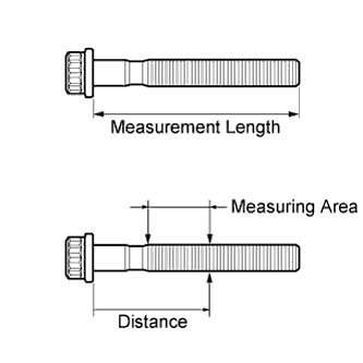 |
Using a vernier caliper, measure the length of the crankshaft bearing cap bolt from the seat to the end.
Using a vernier caliper, measure the diameter of the elongated thread at the measuring area.
| 12. INSPECT CONNECTING ROD BOLT |
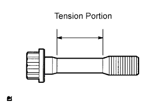 |
Using a vernier caliper, measure the tension portion diameter of the bolt.
| 13. INSPECT NO. 1 OIL NOZZLE SUB-ASSEMBLY |
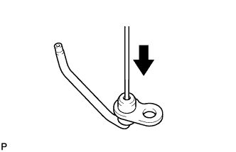 |
Push the check valve with a pin to check if it is stuck.
If stuck, replace the No. 1 oil nozzle.
Push the check valve with a pin to check if it moves smoothly.
If it does not move smoothly, clean or replace the No. 1 oil nozzle.
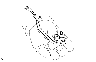 |
Apply air into A. Check that air does not leak through B.
If air leaks, clean or replace the No. 1 oil nozzle.
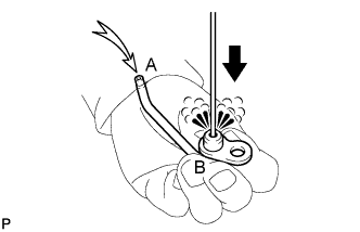 |
Push the check valve while applying air into A. Check that air passes through B.
If air does not pass through B, clean or replace the No. 1 oil nozzle.