 |
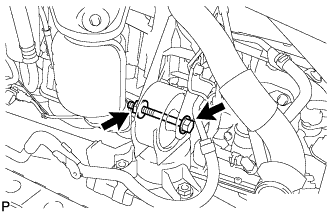
Remove the bolt, nut and crossmember.
CAMSHAFT (for Bank 1) > REMOVAL |
| 1. REMOVE ENGINE WITH TRANSAXLE |
Remove the engine with transaxle (Click here)
| 2. REMOVE FRONT CROSS MEMBER SUB-ASSEMBLY |
|
Remove the bolt, nut and crossmember.
| 3. REMOVE FRONT SUSPENSION CROSSMEMBER SUB-ASSEMBLY |
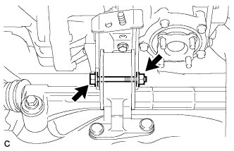 |
Remove the bolt and suspension crossmember.
| 4. REMOVE ENGINE WIRE |
Remove the engine wire from the engine.
| 5. REMOVE STARTER ASSEMBLY |
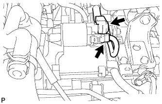 |
Disconnect the starter connector.
Open the terminal cap, remove the nut and disconnect the starter wire.
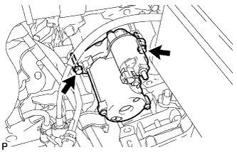 |
Remove the 2 bolts and starter.
| 6. REMOVE AUTOMATIC TRANSAXLE ASSEMBLY |
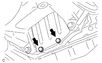 |
Remove the 2 bolts and flywheel housing under cover.
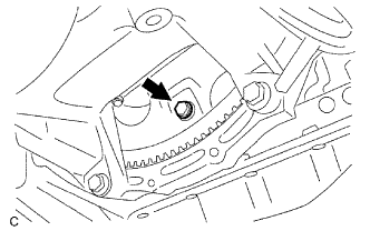 |
Turn the crankshaft to gain access and remove the 6 bolts while holding the crankshaft pulley bolt with a wrench.
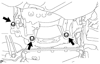 |
Remove the 3 lower side mounting bolts.
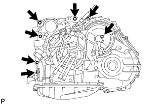 |
Remove the 7 upper side mounting bolts.
Separate and remove the automatic transaxle.
| 7. REMOVE TRANSFER ASSEMBLY |
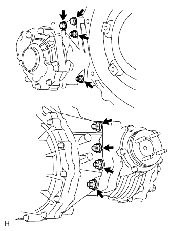 |
except K111F:
Remove the 6 nuts, 2 bolts and transfer from the transaxle.
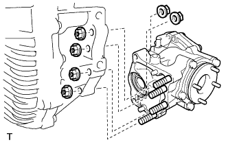 |
for K111F:
Remove the 6 nuts and transfer from the transaxle.
| 8. REMOVE DRIVE PLATE AND RING GEAR SUB-ASSEMBLY |
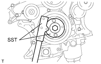 |
Using SST, hold the crankshaft.
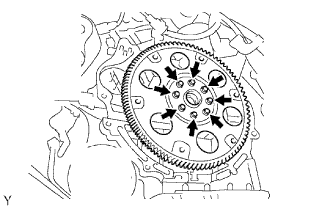 |
Remove the 8 bolts, front spacer, drive plate and rear spacer.
| 9. INSTALL ENGINE TO ENGINE STAND |
Install the engine to an engine stand. Remove the sling device and chain block from the engine.
| 10. REMOVE INTAKE AIR SURGE TANK ASSEMBLY |
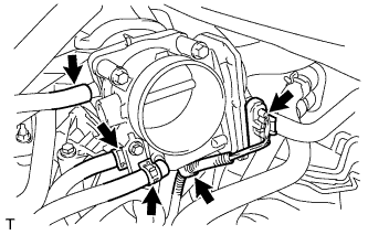 |
Disconnect the 2 water by-pass hoses from the throttle body.
Disconnect the vapor feed hose.
Disconnect the throttle body connector and clamp.
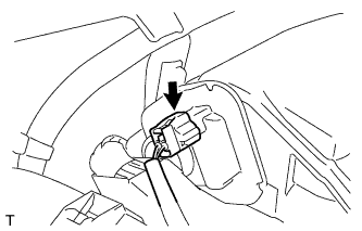 |
Disconnect the connector.
Disconnect the No. 1 ventilation hose and vacuum hose.
Remove the 2 bolts and throttle body bracket.
Remove the 2 bolts and No. 1 surge tank stay.
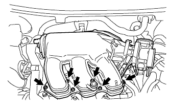 |
Using a 5 mm socket hexagon wrench, remove the 4 bolts.
Remove the 2 nuts and surge tank.
Remove the gasket from the surge tank.
| 11. REMOVE IGNITION COIL ASSEMBLY |
Remove the 6 bolts and 6 coils from the cylinder head.
| 12. REMOVE NO. 2 ENGINE MOUNTING STAY RH |
Remove the bolt and mounting stay.
| 13. REMOVE INTAKE MANIFOLD |
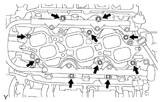 |
Remove the 6 bolts, 4 nuts, intake manifold and 2 gaskets.
| 14. REMOVE MANIFOLD STAY |
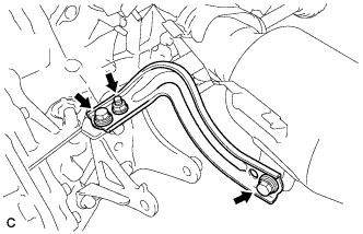 |
Remove the 2 bolts, nut and manifold stay.
| 15. REMOVE EXHAUST MANIFOLD SUB-ASSEMBLY RH |
Disconnect the air fuel ratio sensor connector clamp.
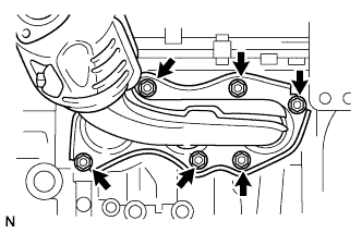 |
Uniformly loosen and remove the 6 nuts.
Remove the manifold and gasket.
| 16. REMOVE V-RIBBED BELT |
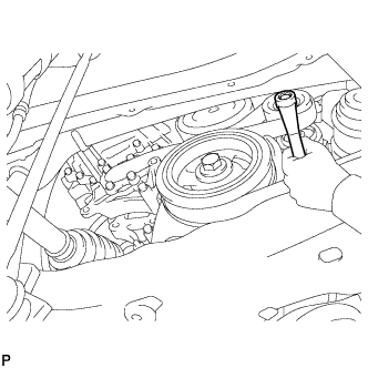 |
Rotate the tensioner pulley counterclockwise to loosen the belt tension. Then remove the V-ribbed belt.
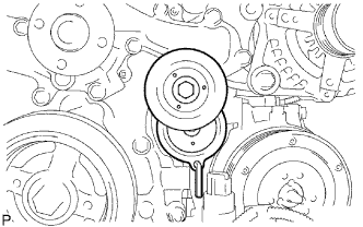 |
While turning the belt tensioner counterclockwise, align its holes, and then insert a 5 mm bi-hexagon wrench into the holes to fix the V-ribbed belt tensioner in place.
| 17. REMOVE NO. 2 IDLER PULLEY SUB-ASSEMBLY |
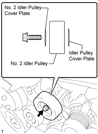 |
Remove the bolt, No. 2 idler pulley cover plate, idler pulley and idler pulley cover plate.
| 18. REMOVE COOLER COMPRESSOR ASSEMBLY |
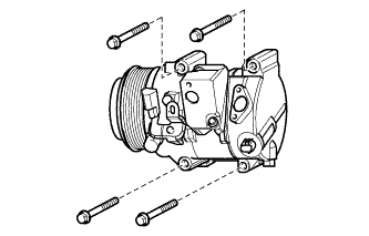 |
Disconnect the connector.
Remove the 4 bolts and cooler compressor.
| 19. REMOVE GENERATOR ASSEMBLY |
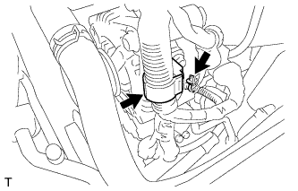 |
Disconnect the 2 wire harness clamps.
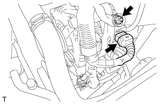 |
Remove the terminal cap.
Remove the nut and disconnect the generator wire from terminal B.
Disconnect the generator connector from the generator.
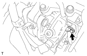 |
Remove the bolt from the cylinder block.
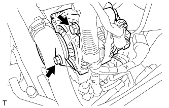 |
Remove the 2 bolts and generator.
| 20. REMOVE OIL DIPSTICK GUIDE |
Remove the dipstick.
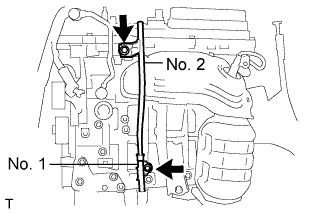 |
Remove the 2 bolts, and the No. 1 and No. 2 guides.
Remove the O-rings from the guide.
| 21. REMOVE NO. 2 MANIFOLD STAY |
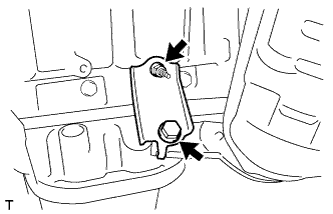 |
Remove the bolt, nut and manifold stay.
| 22. REMOVE NO. 2 EXHAUST MANIFOLD HEAT INSULATOR |
Remove the 3 bolts and insulator.
| 23. REMOVE EXHAUST MANIFOLD SUB-ASSEMBLY LH |
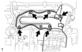 |
Uniformly loosen and remove the 6 nuts.
Remove the manifold and gasket.
| 24. REMOVE V-RIBBED BELT TENSIONER ASSEMBLY |
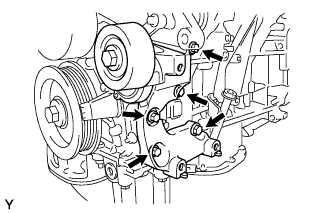 |
Remove the 5 bolts and V-ribbed belt tensioner assembly.
| 25. REMOVE NO. 2 TIMING GEAR COVER |
Remove the 2 bolts and gear cover.
| 26. REMOVE WATER PUMP PULLEY |
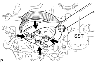 |
Using SST, hold the water pump pulley.
Remove the 4 bolts and water pump pulley.
| 27. REMOVE RADIO SETTING CONDENSER |
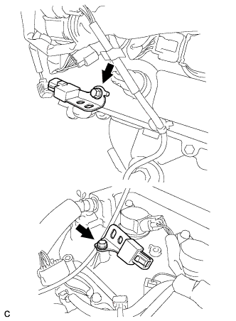 |
Remove the 2 bolts and 2 radio setting condensers.
| 28. REMOVE NO. 1 VACUUM SWITCHING VALVE ASSEMBLY |
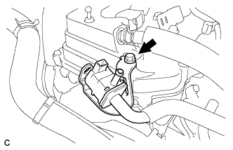 |
Remove the bolt and No. 1 vacuum switching valve.
| 29. REMOVE CRANKSHAFT PULLEY |
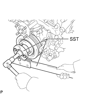 |
Using SST, hold the crankshaft pulley and loosen the pulley bolt. Continue to loosen the bolt until only 2 or 3 threads are screwed into the crankshaft.
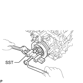 |
Using the pulley set bolt and SST, remove the crankshaft pulley and pulley bolt.
| 30. REMOVE WATER INLET HOUSING |
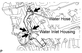 |
Disconnect the water hose.
Remove the 2 bolts, nut and water inlet housing.
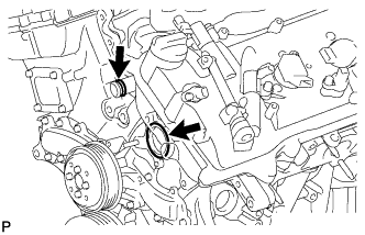 |
Remove the water inlet housing No. 1 gasket and water outlet pipe O-ring.
| 31. REMOVE NO. 2 OIL PAN SUB-ASSEMBLY |
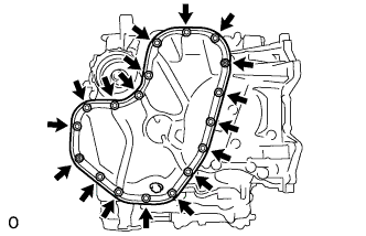 |
Remove the 16 bolts and 2 nuts.
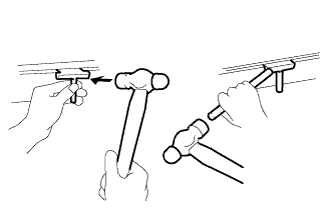 |
Insert the blade of an oil pan seal cutter between the oil pans, cut through the applied sealer and remove the oil pan.
| 32. REMOVE OIL STRAINER SUB-ASSEMBLY |
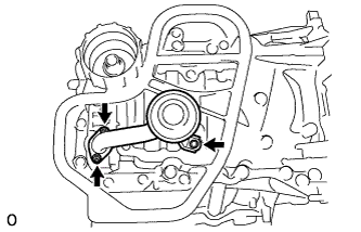 |
Remove the bolt, 2 nuts, oil strainer and gasket.
| 33. REMOVE OIL PAN SUB-ASSEMBLY |
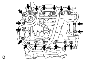 |
Remove the 16 bolts and 2 nuts.
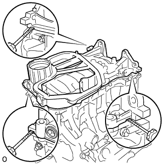 |
Remove the oil pan by prying between the oil pan and cylinder block with a screwdriver.
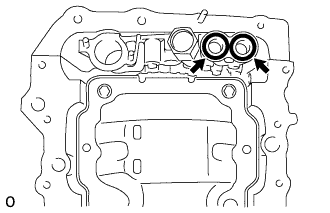 |
Remove the 2 O-rings from the oil pump.
| 34. REMOVE NO. 1 OIL PIPE |
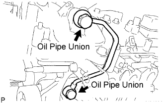 |
Remove the 2 oil pipe unions, gaskets and oil pipe.
Remove the oil control valve filter LH and gaskets.
| 35. REMOVE OIL PIPE |
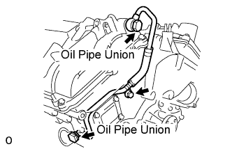 |
Remove the bolt.
Remove the 2 oil pipe unions and oil pipe.
Remove the oil control valve filter RH and gaskets.
| 36. REMOVE CYLINDER HEAD COVER SUB-ASSEMBLY (for Bank 1) |
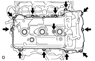 |
Remove the 12 bolts, cylinder head cover and gasket.
| 37. REMOVE CYLINDER HEAD COVER SUB-ASSEMBLY (for Bank 2) |
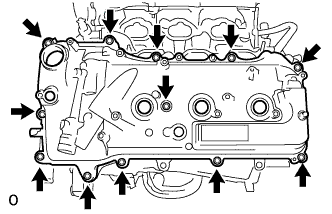 |
Remove the 12 bolts, cylinder head cover and gasket.
| 38. REMOVE TIMING CHAIN COVER SUB-ASSEMBLY |
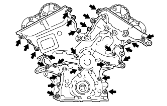 |
Remove the 23 bolts and 2 nuts as shown in the illustration.
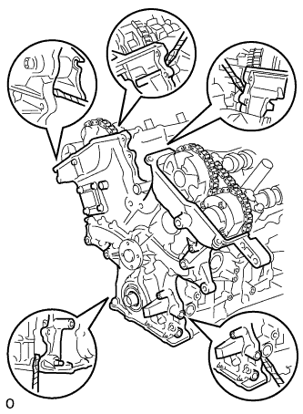 |
Remove the timing chain cover by prying between the timing chain cover and cylinder head or cylinder block with a screwdriver.
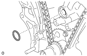 |
Remove the gasket.
| 39. REMOVE TIMING CHAIN COVER OIL SEAL |
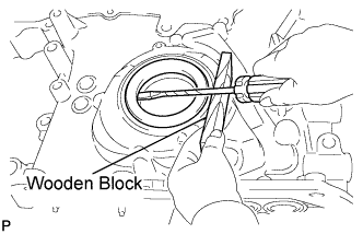 |
Using a screwdriver, pry out the oil seal.
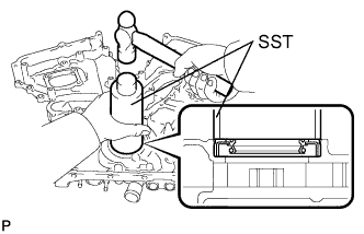 |
Using SST and a hammer, tap in a new oil seal until its surface is flush with the timing chain cover edge.
Apply MP grease to the lip of the oil seal.
| 40. SET NO. 1 CYLINDER TO TDC / COMPRESSION |
Temporarily tighten the pulley set bolt.
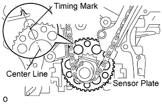 |
Set the timing mark on the crank angle sensor plate to the RH block bore center line (TDC / compression).
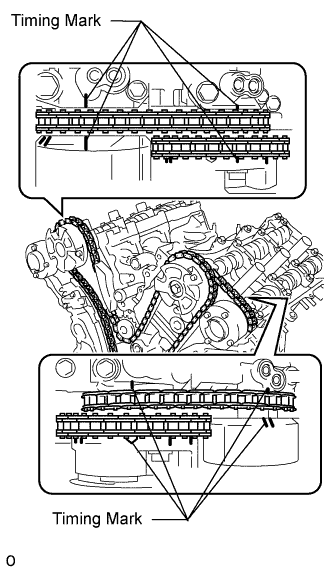 |
Check that the timing marks of the camshaft timing gears are aligned with the timing marks of the bearing cap as shown in the illustration. If not, turn the crankshaft 1 revolution (360°) and align the timing marks as in the previous step.
| 41. REMOVE NO. 1 CHAIN TENSIONER ASSEMBLY |
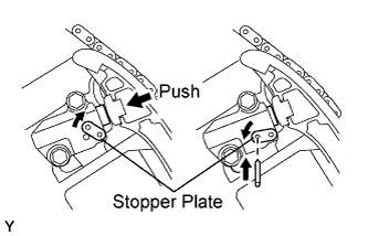 |
Move the stopper plate upward to release the lock, and push the plunger deep into the tensioner.
Move the stopper plate downward to set the lock, and insert a hexagon wrench into the stopper plate hole.
Remove the 2 bolts and chain tensioner.
| 42. REMOVE CHAIN TENSIONER SLIPPER |
| 43. REMOVE NO. 1 CHAIN SUB-ASSEMBLY |
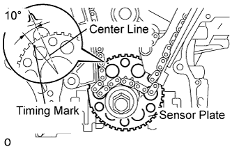 |
Turn the crankshaft counterclockwise 10° to loosen the chain of the crankshaft timing gear.
Remove the chain from the crankshaft timing gear and place it on the crankshaft.
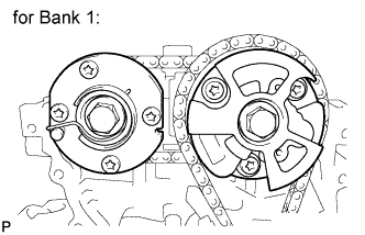 |
Turn the camshaft timing gear on the RH bank clockwise (approximately 60°) and set it as shown in the illustration. Be sure to loosen the chain between the center banks.
Remove the chain.
| 44. REMOVE IDLE SPROCKET ASSEMBLY |
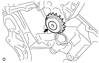 |
Using a 10 mm hexagon wrench, remove the No. 2 idle gear shaft, idle sprocket and No. 1 idle gear shaft.
| 45. REMOVE CAMSHAFT TIMING GEARS AND NO. 2 CHAIN (for Bank 1) |
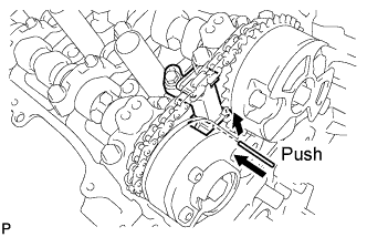 |
While raising up the No. 2 chain tensioner, insert a pin of φ1.0 mm (0.039 in.) into the hole to fix it in place.
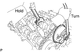 |
Hold the hexagonal portion of the camshaft with a wrench, and remove the 2 bolts and 2 camshaft timing gears.
Remove the No. 2 chain.
| 46. REMOVE NO. 2 CHAIN TENSIONER ASSEMBLY |
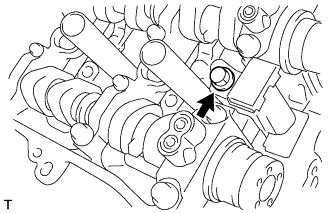 |
Remove the bolt and chain tensioner.
| 47. REMOVE CAMSHAFT BEARING CAP (for Bank 1) |
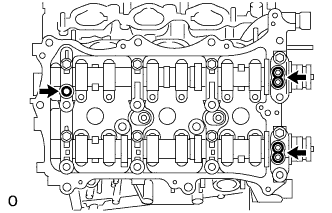 |
Remove the 3 gaskets.
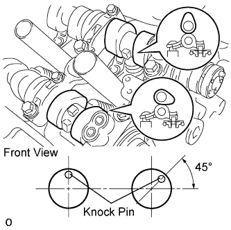 |
Make sure that the knock pin of the camshaft is positioned as shown in the illustration.
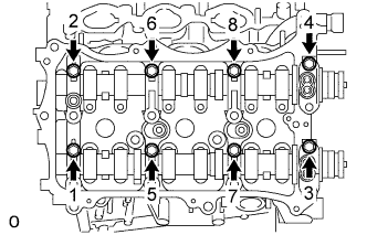 |
Uniformly loosen and remove the 8 bearing cap bolts in several steps and in the sequence shown in the illustration.
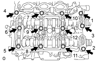 |
Uniformly loosen and remove the 12 bearing cap bolts in several steps and in the sequence shown in the illustration.
Remove the 5 bearing caps.
| 48. REMOVE NO. 1 CAMSHAFT |
Remove the No. 1 camshaft.
| 49. REMOVE NO. 2 CAMSHAFT |
Remove the No. 2 camshaft.
| 50. REMOVE CAMSHAFT HOUSING SUB-ASSEMBLY (for Bank 1) |
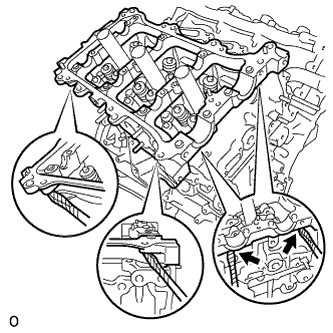 |
Remove the camshaft housing by prying between the cylinder head and camshaft housing with a screwdriver.