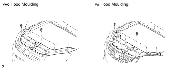
Remove the 9 clips and radiator support opening cover.
CONTINUOUSLY VARIABLE VALVE LIFT CONTROLLER > REMOVAL |
| 1. REMOVE RADIATOR SUPPORT OPENING COVER |
Remove the 9 clips and radiator support opening cover.
| 2. DISCONNECT CABLE FROM NEGATIVE BATTERY TERMINAL |
| 3. REMOVE NO. 2 CYLINDER HEAD COVER |
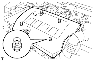 |
Hold the rear of the cover and raise it to detach the 2 clips on the rear of the cover. Continue to raise the cover to detach the 2 clips on the front of the cover and remove the cover.
| 4. REMOVE AIR CLEANER CAP SUB-ASSEMBLY |
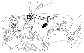 |
Disconnect the mass air flow meter connector.
Detach the clamp.
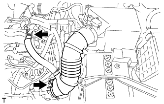 |
Disconnect the No. 2 ventilation hose from the cylinder head cover.
Squeeze the taps of the air cleaner hose clamp, and then disconnect the air cleaner hose from the throttle body.
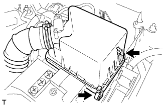 |
Detach the 2 hook clamps, and then remove the air cleaner cap and hose.
| 5. REMOVE AIR CLEANER CASE SUB-ASSEMBLY |
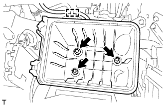 |
Disconnect the wire harness clamp from the air cleaner case.
Remove the 3 bolts and air cleaner case.
| 6. REMOVE BATTERY CLAMP SUB-ASSEMBLY |
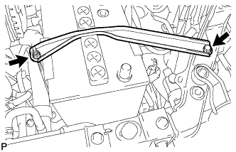 |
Remove the bolt and loosen the nut.
Detach the hook of the battery clamp from the front battery bracket, and then remove the battery clamp.
| 7. REMOVE BATTERY |
| 8. REMOVE BATTERY TRAY |
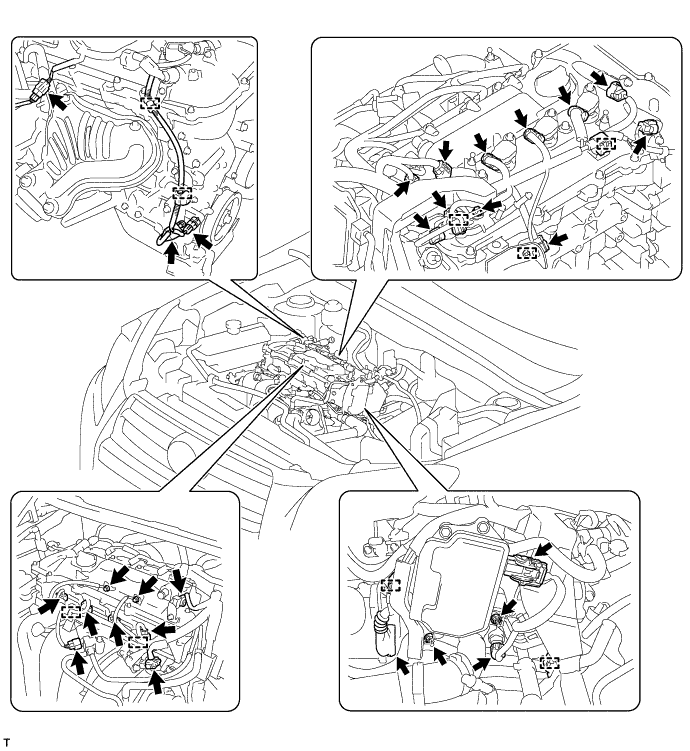
| 9. DISCONNECT ENGINE WIRE |
Detach the 9 clamps, and then disconnect the connectors.
Remove the 3 bolts and 2 nuts, and then disconnect the engine wire.
| 10. REMOVE IGNITION COIL ASSEMBLY |
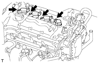 |
Remove the 4 bolts and 4 ignition coils.
| 11. REMOVE AIR TUBE |
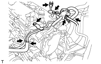 |
Disconnect the fuel vapor feed hose from the purge VSV.
Disconnect the 2 union to connector tube hoses.
Disconnect the No. 2 air hose and No. 1 fuel vapor feed hose.
Remove the 2 bolts and air tube.
| 12. REMOVE CYLINDER HEAD COVER SUB-ASSEMBLY |
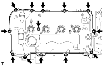 |
Remove the 13 bolts, seal washer and cylinder head cover.
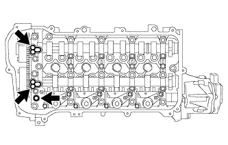 |
Remove the 3 gaskets from the camshaft bearing cap.
| 13. REMOVE CYLINDER HEAD COVER GASKET |
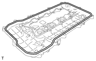 |
Remove the cylinder head cover gasket.
| 14. REMOVE CONTINUOUSLY VARIABLE VALVE LIFT CONTROLLER ASSEMBLY |
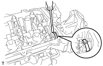 |
Using a screwdriver, slide the valve lift control actuator connector clip from the valve lift control actuator connector.
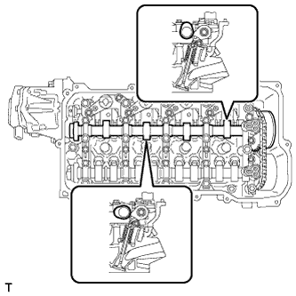 |
Rotate the crankshaft clockwise until the intake camshaft position at the No. 1 cylinder and No. 3 cylinder is as shown in the illustration.
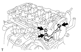 |
Remove the bolt, 2 nuts and wire harness clamp bracket.
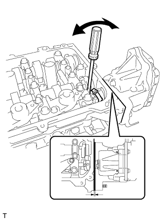 |
Using a screwdriver, lightly pry the valve lift control actuator connector to make a space between the continuously variable valve lift controller assembly and camshaft housing.
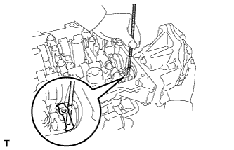 |
Using a magnet hand, remove the straight pin from the valve lift control actuator connector.
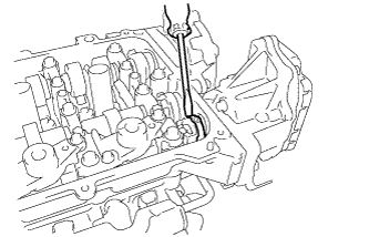 |
Using a screwdriver, remove the valve lift control actuator connector clip from the valve lift control actuator connector.
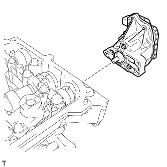 |
Remove the continuously variable valve lift controller assembly from the camshaft housing.
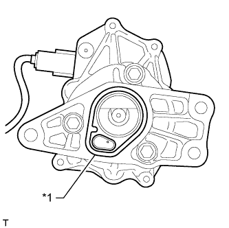 |
Remove the O-ring to the continuously variable valve lift controller assembly.
| *1 | O-Ring |
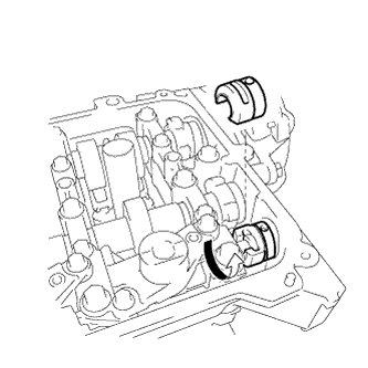 |
Rotate the valve lift control actuator connector and remove it from the valve rocker shaft.