NM30B0U
_51
Engine / Hybrid System
_008617
2AR-FE ENGINE CONTROL
_0048043
SFI SYSTEM
DE
DETAILS
F
2AR-FE ENGINE CONTROL SFI SYSTEM DETAILS TUMBLE CONTROL VALVE POSITION SENSOR
CONSTRUCTION
a.
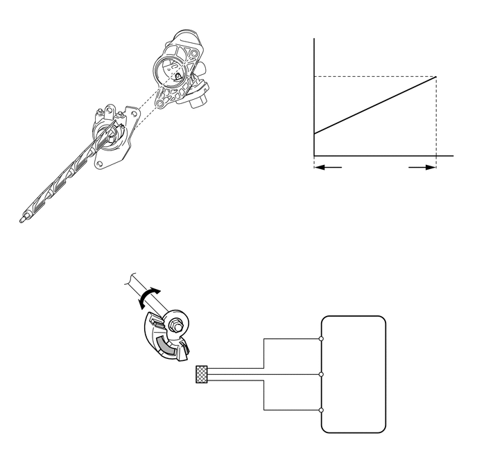
The non-contact type tumble control valve position sensor uses a Hall IC. It detects the tumble control valve opening angle.
b.
The sensor converts the magnetic flux density that changes when the magnetic yoke (located on the same axis as the tumble control valve shaft) rotates around the Hall IC into electric signals and sends them to the ECM.
0.198,3.708 6.948,6.698
6.75,2.99
2.469,0.802 2.188,0.375
2.188,0.375 1.948,0.375
true
2.656,1.125 2.771,1.813
2.771,1.813 2.99,1.813
true
1.792,2.021 1.906,2.708
1.906,2.708 2.125,2.708
true
2.208,4.979 1.979,4.75
1.979,4.75 1.719,4.75
true
2.792,5.229 2.958,4.896
2.958,4.896 3.188,4.896
true
1.354,0.281 1.979,0.594
0.625,0.313
10
Actuator
2.865,5.792 3.354,6.083
0.49,0.292
10
Hall IC
2.156,2.615 3.208,3.063
1.052,0.448
10
Magnetic Yoke
4.031,1.302 4.677,2.073
0.646,0.771
10
Output Voltage (V)
4.396,2.656 5.281,3.052
0.885,0.396
10
Fully Closed
6.26,2.667 6.99,3.031
0.729,0.365
10
Fully Open
4.615,3.031 6.917,3.427
2.302,0.396
10
Tumble Control Valve Opening Angle
3.229,4.813 3.76,5.177
0.531,0.365
10
Magnet
5.135,5.385 5.479,5.729
0.344,0.344
10
ECM
3.031,1.75 3.521,2.042
0.49,0.292
10
Hall IC
0.719,4.677 1.771,5.125
1.052,0.448
10
Magnetic Yoke
4.406,5.125 4.802,5.365
0.396,0.24
10
VCIA
4.427,5.667 4.823,5.906
0.396,0.24
10
IAC1
4.427,6.188 4.823,6.427
0.396,0.24
10
EIA1
0.375,3.76 2.677,4.156
2.302,0.396
10
System Diagram