Home › Drivetrain › GF1A TRANSFER / 4WD / AWD › DYNAMIC TORQUE CONTROL AWD SYSTEM
NM30B0U _52 Drivetrain _008839 GF1A TRANSFER / 4WD / AWD _0060878 DYNAMIC TORQUE CONTROL AWD SYSTEM DE DETAILS F

GF1A TRANSFER / 4WD / AWD  DYNAMIC TORQUE CONTROL AWD SYSTEM  DETAILS  TRANSFER  


CONSTRUCTION


a.

A side-to-side split transfer case made of aluminum is used to achieve a compact and lightweight construction.


b.

A unit ball bearing is used for supporting the driven pinion gear to achieve a compact and lightweight construction.


c.

The ring gear and the transfer ring gear mounting case are joined with splines to achieve a compact construction.


d.

Drive force input into the differential is redirected 90 degrees and output to the propeller shaft by the transfer.


e.

The offset between the transfer ring gear and the transfer driven pinion gear is increased, the distance between the driven pinion bearings is reduced and a small-diameter ring gear mount bearing is used. As a result, the transfer is easier to install.
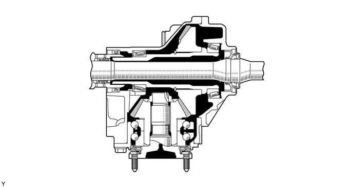
X111797
2.75,0.979 2.323,0.448 true 2.573,1.198 1.646,0.99 true 2.333,1.823 1.542,1.938 true 2.698,2.542 1.667,2.979 true 2.677,2.979 2.167,3.5 true 4.354,3.25 3.302,2.677 true 4.615,2.74 3.531,2.5 true 5.208,1.896 4.75,1.698 true 5.917,1.188 5.146,1.323 true 5.167,0.479 4.552,0.635 true 4.344,0.229 3.927,0.615 true 2.156,0.313 2.469,0.469 0.313,0.156 10 *1 1.458,0.875 1.771,1.031 0.313,0.156 10 *2 1.375,1.865 1.688,2.021 0.313,0.156 10 *3 1.51,2.917 1.823,3.073 0.313,0.156 10 *4 4.396,3.198 4.708,3.354 0.313,0.156 10 *5 4.667,2.677 4.979,2.833 0.313,0.156 10 *6 5.958,1.104 6.271,1.26 0.313,0.156 10 *7 5.208,0.385 5.521,0.542 0.313,0.156 10 *8 4.375,0.083 4.688,0.24 0.313,0.156 10 *9 2.01,3.448 2.323,3.604 0.313,0.156 10 *3 5.25,1.844 5.563,2 0.313,0.156 10 *3
*1 Transfer Case *2 Transfer Ring Gear Mounting Case
*3 Oil Seal *4 Unit Ball Bearing
*5 Transfer Driven Pinion Shaft *6 Transfer Driven Pinion Gear
*7 Drive Shaft *8 Transfer Cover
*9 Transfer Ring Gear - -


OPERATION


a.

Transfer Power Flow

i.

The illustration below shows the flow of power from the transaxle:
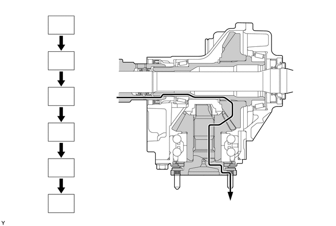
X111798
2.302,1.042 2.646,1.427 true 3.729,0.802 3.875,1.469 true 5.042,0.833 5.708,0.365 true 4.76,2.729 5.813,2.948 true 4.531,2.948 5.531,3.469 true 1.219,0.448 1.531,0.604 0.313,0.156 10 *1 1.229,1.208 1.542,1.365 0.313,0.156 10 *2 1.229,1.979 1.542,2.135 0.313,0.156 10 *3 1.24,2.74 1.552,2.896 0.313,0.156 10 *4 1.229,3.49 1.542,3.646 0.313,0.156 10 *5 1.24,4.26 1.552,4.417 0.313,0.156 10 *6 2.146,0.875 2.458,1.031 0.313,0.156 10 *1 3.635,0.604 3.948,0.76 0.313,0.156 10 *2 5.75,0.25 6.063,0.406 0.313,0.156 10 *3 5.865,2.875 6.177,3.031 0.313,0.156 10 *4 5.573,3.427 5.885,3.583 0.313,0.156 10 *5 4.833,4.302 5.146,4.458 0.313,0.156 10 *6
*1 Transaxle Differential Case *2 Transfer Ring Gear Mounting Case
*3 Transfer Ring Gear *4 Transfer Driven Pinion Gear
*5 Transfer Driven Pinion Shaft *6 Propeller Shaft
V100135

Power Flow - -