RM30B0U
_51
Engine / Hybrid System
_009233
2AR-FE COOLING
_0050394
RELAY
G
2AR-FE COOLING RELAY ON-VEHICLE INSPECTION
PROCEDURE

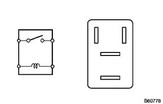
 1.INSPECT NO. 1 COOLING FAN RELAY (FAN NO. 1)
a.
2.604,0.698 2.958,0.5
true
2.458,1.135 2.958,0.917
true
2.448,1.635 2.948,1.375
true
2.031,0.667 1.719,0.51
true
3,0.396 3.115,0.594
0.115,0.198
10
2
3.01,0.833 3.125,1.031
0.115,0.198
10
5
2.99,1.292 3.104,1.49
0.115,0.198
10
3
1.583,0.406 1.698,0.604
0.115,0.198
10
1
0.229,1.313 0.344,1.51
0.115,0.198
10
1
1.167,0.771 1.281,0.969
0.115,0.198
10
5
0.229,0.771 0.344,0.969
0.115,0.198
10
3
1.177,1.302 1.292,1.5
0.115,0.198
10
2
Measure the resistance according to the value(s) in the table below.
- Standard Resistance:
Tester Connection Condition Specified Condition 3 - 5 Battery voltage not applied to terminals 1 and 2 10 kΩ or higher Battery voltage applied to terminals 1 and 2 Below 1 Ω
If the result is not as specified, replace the No. 1 cooling fan relay.
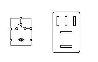
2.INSPECT NO. 2 COOLING FAN RELAY (FAN NO. 2)
a.
2.031,0.646 1.875,0.521
1.875,0.521 1.708,0.521
true
2.427,1.125 3.01,1.125
true
2.396,1.625 3.021,1.625
true
2.948,0.5 2.781,0.5
2.781,0.5 2.615,0.667
true
2.646,0.167 2.479,0.167
2.479,0.167 2.313,0.667
true
0.24,0.938 0.396,1.115
0.156,0.177
10
5
0.229,1.333 0.385,1.51
0.156,0.177
10
1
0.708,0.406 0.948,0.563
0.24,0.156
10
4
1.135,0.917 1.292,1.094
0.156,0.177
10
3
1.146,1.323 1.302,1.5
0.156,0.177
10
2
1.604,0.448 1.76,0.625
0.156,0.177
10
1
2.688,0.094 2.844,0.271
0.156,0.177
10
4
3,0.427 3.156,0.604
0.156,0.177
10
2
3.063,1.563 3.219,1.74
0.156,0.177
10
3
3.042,1.052 3.198,1.229
0.156,0.177
10
5
Measure the resistance according to the value(s) in the table below.
- Standard Resistance:
Tester Connection Condition Specified Condition 3 - 4 Battery voltage not applied between terminals 1 and 2 Below 1 Ω Battery voltage applied between terminals 1 and 2 10 kΩ or higher 3 - 5 Battery voltage not applied between terminals 1 and 2 10 kΩ or higher Battery voltage applied between terminals 1 and 2 Below 1 Ω
If the result is not as specified, replace the No. 2 cooling fan relay.
3.INSPECT NO. 3 COOLING FAN RELAY (FAN NO. 3)
a.
2.604,0.698 2.958,0.5
true
2.458,1.135 2.958,0.917
true
2.448,1.635 2.948,1.375
true
2.031,0.667 1.719,0.51
true
3,0.396 3.115,0.594
0.115,0.198
10
2
3.01,0.833 3.125,1.031
0.115,0.198
10
5
2.99,1.292 3.104,1.49
0.115,0.198
10
3
1.583,0.406 1.698,0.604
0.115,0.198
10
1
0.229,1.313 0.344,1.51
0.115,0.198
10
1
1.167,0.771 1.281,0.969
0.115,0.198
10
5
0.229,0.771 0.344,0.969
0.115,0.198
10
3
1.177,1.302 1.292,1.5
0.115,0.198
10
2
Measure the resistance according to the value(s) in the table below.
- Standard Resistance:
Tester Connection Condition Specified Condition 3 - 5 Battery voltage not applied to terminals 1 and 2 10 kΩ or higher Battery voltage applied to terminals 1 and 2 Below 1 Ω
If the result is not as specified, replace the No. 3 cooling fan relay.