RM30B0U
_59
Vehicle Exterior
_010076
WINDOW / GLASS
_0054878
WINDSHIELD DEICER SWITCH
G
WINDOW / GLASS WINDSHIELD DEICER SWITCH ON-VEHICLE INSPECTION
PROCEDURE

 1.CHECK FRONT WIPER DEICER SWITCH
a.
Disconnect the windshield deicer switch connector.
b.
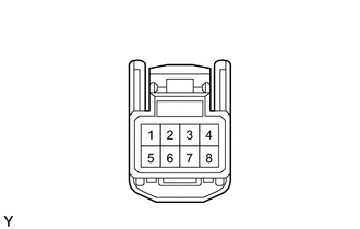
1.396,1.208 0.958,1.208
false
1.396,1.438 0.979,1.563
false
1.635,1.49 2.354,1.729
false
2.052,1.198 2.365,0.969
false
2.052,1.406 2.427,1.313
false
0.563,1.115 0.917,1.323
0.354,0.208
10
ILL+
2.385,1.646 2.74,1.854
0.354,0.208
10
ILL-
2.375,0.823 2.729,1.031
0.354,0.208
10
IG
2.49,1.208 2.844,1.417
0.354,0.208
10
D
0.771,1.521 0.99,1.708
0.219,0.188
10
E
0.052,0.052 0.365,0.208
0.313,0.156
10
*a
| *a | Rear view wire harness connector
(to Front wiper Deicer Switch) |
Measure the voltage and resistance according to the value(s) in the table below.
- Standard Voltage:
Tester Connection Condition Specified Condition 1 (ILL+) - 6 (ILL-) Headlight dimmer switch OFF → ON Below 1 V → 10 to 14 V 8 (D) - 5 (E) Ignition switch ON 10 to 14 V 4 (IG) - 5 (E) Ignition switch ON 10 to 14 V
- Standard Resistance:
Tester Connection Condition Specified Condition 6 (ILL-) - Body ground Always Below 1 Ω 5 (E) - Body ground Always Below 1 Ω
c.
Reconnect the windshield deicer connector.
d.
2.146,1.052 1.792,0.865
false
2.146,1.438 1.781,1.635
false
2.729,1.438 3.021,1.667
false
1.552,0.76 1.771,0.969
0.219,0.208
10
false
IG
1.604,1.573 1.792,1.75
0.188,0.177
10
false
D
3.063,1.604 3.219,1.781
0.156,0.177
10
false
E
0.073,0.052 0.385,0.25
0.313,0.198
10
false
*a
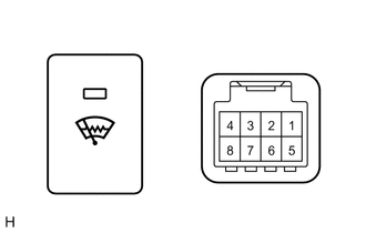
| *a | Component wit harness connected
(Front Wiper Deicer Switch) |
Measure the voltage according to the value(s) in the table below.
- Standard Voltage:
Tester Connection Condition Specified Condition 8 (D) - 5 (E) Ignition switch ON, windshield deicer switch OFF → ON 10 to 14 V → Below 1 V (after 15 +/-3 minutes: 10 to 14 V) 4 (IG) - 5 (E) Ignition switch ON, windshield deicer switch ON 10 to 14 V → Below 1 V
e.
2.521,0.844 2.521,0.927
2.521,0.927 1.354,0.927
true
0.938,0.583 2.417,0.583
false
0.771,0.5 1.083,0.656
0.313,0.156
10
*1
1.167,0.844 1.479,1
0.313,0.156
10
*2
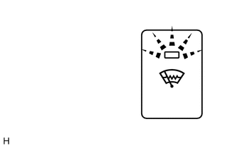
| *1 | Illumination Area |
| *2 | ON/OFF Indicator |
Check the ON/OFF indicator of the switch.
i.
Push the switch several times. Check that the ON/OFF indicator illuminates or turns off according to the switch operation.
f.
2.458,0.75 2.458,0.583
2.458,0.583 0.75,0.583
true
2.25,1 1.083,1
true
0.583,0.51 0.896,0.667
0.313,0.156
10
*1
0.906,0.917 1.219,1.073
0.313,0.156
10
*2
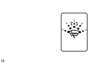
| *1 | ON/OFF Indicator |
| *2 | Illumination Area |
Check the illumination area of the switch.
i.
Check that the ON/OFF indicator illuminates or turns off according to the switch operation.