BRAKE SYSTEM (OTHER) BRAKE MASTER CYLINDER INSPECTION
PROCEDURE

 1.CHAECK AND ADJUST BRAKE BOOSTER PUSH ROD
Apply chalk to the tip of the accessory tool.
- HINT:
-
An accessory tool is included with a new brake master cylinder sub-assembly.
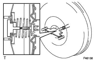
| *1 | Accessory Tool |
| *a | Apply Chalk |
Place the accessory tool on the brake booster assembly.
Measure the clearance between the brake booster push rod and accessory tool.
- Standard clearance:
0 mm (0 in.)
- HINT:
-
Adjust the clearance in the following cases:
- ·
If there is a clearance between the accessory tool and the shell of the brake booster (floating accessory tool), the push rod is protruding too far.
- ·
If the chalk does not stick on the tip of the brake booster push rod, the push rod protrusion is insufficient.
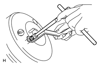
If the clearance is not within the standard, adjust the length by holding the rod using SST and turning the tip of the rod using a 7 mm socket driver.
- SST
- 09737-00020
- NOTICE:
-
Check the push rod clearance again after adjusting.