CRUISE CONTROL LANE RECOGNITION CAMERA SENSOR INSTALLATION
CAUTION / NOTICE / HINT
- NOTICE:
- ·
If the lane departure warning camera bracket is deformed or damaged, replace it together with the windshield glass.
·If the windshield glass is replaced on a vehicle equipped with an lane departure alert camera, make sure to use a Toyota genuine part, as the camera may not be able to be installed due to a missing bracket or the lane departure alert system may not operate properly due to a difference in the transmissivity or ceramic line shape.
·If the lane departure warning camera is dropped, replace it with a new one.
PROCEDURE

 1.INSTALL LANE DEPARTURE WARNING CAMERA
When using a new lane departure warning camera:
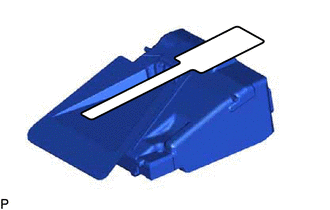
Remove the protective film.
- NOTICE:
-
Do not touch the camera lens after removing the protective film.
Attach the 2 guides as shown in the illustration.
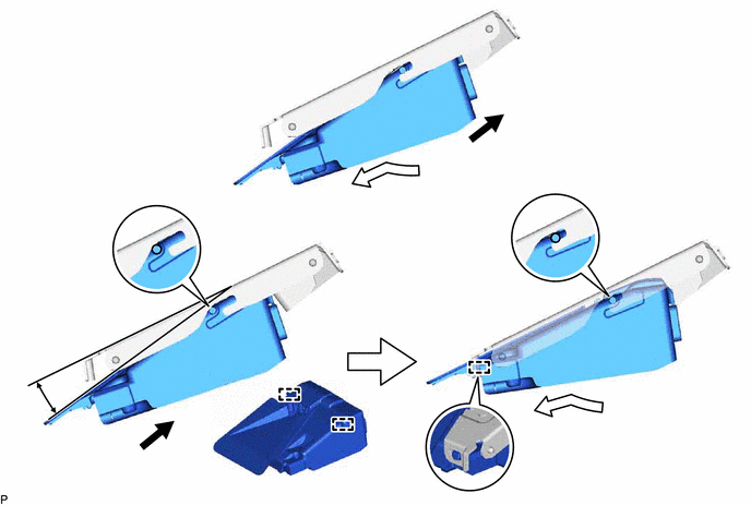
- NOTICE:
-
Do not touch the camera lens.
Attach the guide as shown in the illustration.
Connect the connector and install the lane departure warning camera.
2.INSTALL LANE DEPARTURE WARNING CAMERA COVER
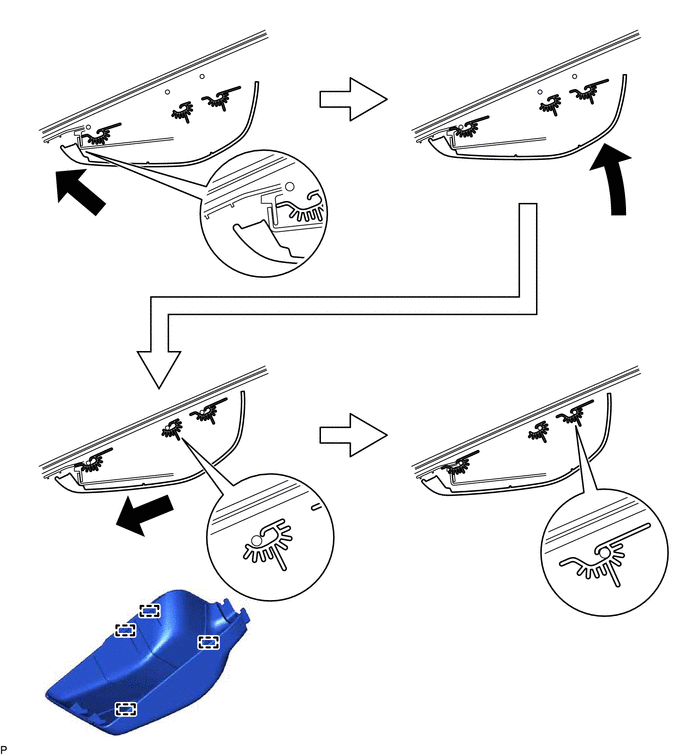
Attach the 4 guides and install the lane departure warning camera cover as shown in the illustration.
3.INSPECT LANE DEPARTURE WARNING CAMERA COVER
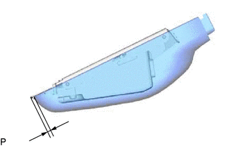
Check the clearance of area A.
| Area | Measurement |
| A | 0 to 2 mm (0 to 0.0787 in.) |
- HINT:
-
If the result is not as specified, the guides are not attached properly. Reinstall the lane departure warning camera cover.
4.INSTALL INNER REAR VIEW MIRROR ASSEMBLY
w/o EC Mirror:
Click hereVehicle Interior>MIRROR (INT)>INNER REAR VIEW MIRROR>INSTALLATION
w/ EC Mirror:
Click hereVehicle Interior>MIRROR (INT)>INNER REAR VIEW MIRROR>INSTALLATION
5.INSTALL RAIN SENSOR COVER
Attach the 2 claws to install the rain sensor cover.
6.ADJUST LANE DEPARTURE WARNING CAMERA