Home › Engine / Hybrid System › 1AD-FTV INTAKE / EXHAUST › INTAKE SYSTEM › 2012.12–2015.10
NM3090E _51 Engine / Hybrid System _008656 1AD-FTV INTAKE / EXHAUST _0048083 INTAKE SYSTEM DE DETAILS F

1AD-FTV INTAKE / EXHAUST  INTAKE SYSTEM  DETAILS  TURBOCHARGER  


CONSTRUCTION


a.

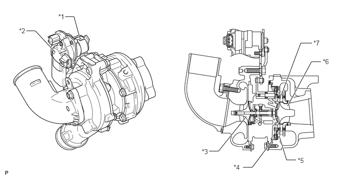
The variable nozzle vane type turbocharger sub-assembly consists primarily of a turbine, nozzle vane, unison ring, nozzle ring and turbocharger variable nozzle motor (DC motor and nozzle vane position sensor).


b.

This turbocharger has achieved improvements in low-speed torque, fuel consumption and emission reduction. Both torque improvement at low speed and low fuel consumption are achieved by using a small size turbocharger because it enables high boost pressure at low speed. Response in boost pressure change is improved by changing control from the actuator to DC motor.
W106011C02
1.698,0.813 1.573,0.354 1.573,0.354 1.385,0.354 true 5.979,2.031 6.396,0.917 6.396,0.917 6.635,0.917 true 6.115,2.26 6.625,1.313 6.625,1.313 6.823,1.313 true 5.24,2.479 4.646,3.219 4.646,3.219 4.448,3.219 true 1.177,1.115 0.75,0.656 0.75,0.656 0.563,0.656 true 5.833,2.938 5.365,3.563 5.365,3.563 5.167,3.563 true 5.938,2.896 6.094,3.406 6.094,3.406 6.292,3.406 true 1.24,0.271 1.469,0.479 0.229,0.208 10 *1 6.667,0.833 6.896,1.042 0.229,0.208 10 *7 6.865,1.229 7.094,1.438 0.229,0.208 10 *6 4.292,3.146 4.521,3.354 0.229,0.208 10 *3 0.406,0.573 0.635,0.781 0.229,0.208 10 *2 4.969,3.479 5.198,3.688 0.229,0.208 10 *4 6.333,3.333 6.563,3.542 0.229,0.208 10 *5
*1 DC Motor *2 Nozzle Vane Position Sensor
*3 Impeller Wheel *4 VGS Link Plate
*5 Nozzle Ring *6 Turbine Wheel
*7 Nozzle Vane - -


c.

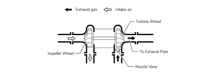
The exhaust gas from the exhaust manifold goes through the nozzle vane inside the turbocharger housing, and flows to the exhaust pipe through the turbine. The speed of the turbine (supercharging pressure) differs depending on the flow velocity of the exhaust gas going through the turbine. The flow velocity of the exhaust gas is controlled by the nozzle vane opening.
W100374E02
2.99,1.406 2.771,1.844 2.771,1.844 2.594,1.844 true 4.24,1.208 4.521,0.74 4.521,0.74 4.656,0.74 true 4.469,1.323 4.583,1.781 4.583,1.781 4.792,1.781 true 4.115,1.823 4.438,2.302 4.438,2.302 4.646,2.302 true 2.542,0.24 3.573,0.594 1.031,0.354 10 : Exhaust gas 3.927,0.24 4.677,0.563 0.75,0.323 10 : Intake air 1.646,1.76 2.708,2.083 1.063,0.323 10 Impeller Wheel 4.698,0.656 5.698,1.01 1,0.354 10 Turbine Wheel 4.833,1.698 5.979,2.01 1.146,0.313 10 To Exhaust Pipe 4.688,2.219 5.594,2.552 0.906,0.333 10 Nozzle Vane


OPERATION


a.

At Low Load Range or Low Speed Range

i.

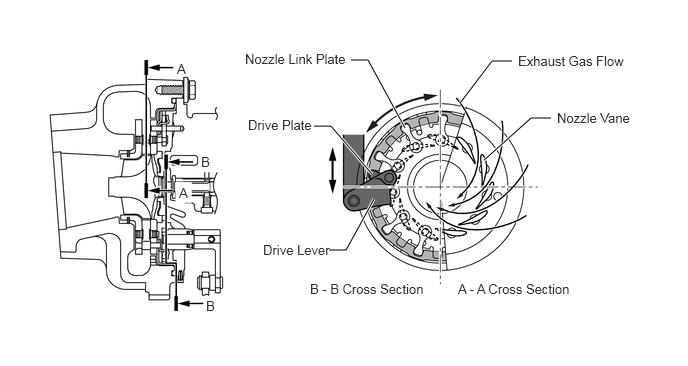
The DC motor moves the drive lever in the closing direction of the nozzle vanes in accordance with signals from the ECM.


ii.

This results in increasing the velocity of the exhaust gas flowing to the turbine, as well as the speed of the turbine. As a result, torque is improved when the engine is running at low speeds.
W110556E01
3.427,2.604 3.604,2.604 3.604,2.604 3.896,2.073 true 3.271,1.313 3.448,1.313 3.448,1.313 3.875,1.813 true 3.656,0.625 3.833,0.625 3.833,0.625 4.219,1.333 true 5.042,1.667 5.531,1.229 5.531,1.229 5.74,1.229 true 4.792,1.073 5.125,0.635 5.125,0.635 5.333,0.635 true 2.552,0.531 3.802,0.76 1.25,0.229 10 Nozzle Link Plate 5.396,0.552 6.646,0.781 1.25,0.229 10 Exhaust Gas Flow 5.802,1.146 6.677,1.396 0.875,0.25 10 Nozzle Vane 4.771,2.927 6.021,3.156 1.25,0.229 10 A - A Cross Section 3.229,2.927 4.479,3.156 1.25,0.229 10 B - B Cross Section 2.583,1.219 3.344,1.458 0.76,0.24 10 Drive Plate 2.74,2.521 3.5,2.76 0.76,0.24 10 Drive Lever 2.146,3.104 2.354,3.344 0.208,0.24 10 B 2.094,1.604 2.302,1.844 0.208,0.24 10 B 1.865,1.927 2.073,2.167 0.208,0.24 10 A 1.844,0.635 2.052,0.875 0.208,0.24 10 A


b.

At High Load Range or High Speed Range

i.

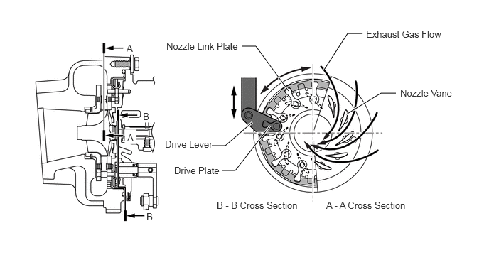
When the engine is running in high load range or high speed range, the nozzle vanes are opened and the discharging pressure is maintained at a certain level.
W110557E01
3.25,2.5 3.448,2.5 3.448,2.5 3.958,1.844 true 3.104,2.135 3.302,2.135 3.302,2.135 3.698,1.792 true 3.552,0.677 3.75,0.677 3.75,0.677 4.229,1.333 true 4.75,1.021 5.094,0.49 5.094,0.49 5.313,0.49 true 5.073,1.677 5.583,1.365 5.583,1.365 5.802,1.365 true 4.781,2.927 6.115,3.198 1.333,0.271 10 A - A Cross Section 3.177,2.927 4.51,3.198 1.333,0.271 10 B - B Cross Section 2.417,2.031 3.188,2.26 0.771,0.229 10 Drive Lever 2.552,2.417 3.323,2.646 0.771,0.229 10 Drive Plate 2.438,0.594 3.677,0.833 1.24,0.24 10 Nozzle Link Plate 5.365,0.417 6.604,0.656 1.24,0.24 10 Exhaust Gas Flow 5.865,1.281 6.771,1.521 0.906,0.24 10 Nozzle Vane 1.854,0.625 2.083,0.844 0.229,0.219 10 A 1.865,1.938 2.094,2.156 0.229,0.219 10 A 2.094,1.625 2.323,1.844 0.229,0.219 10 B 2.146,3.094 2.375,3.313 0.229,0.219 10 B